Electronic endoscope system with color-balance alteration process

a color balance and endoscope technology, applied in the field of electronic endoscope systems, can solve the problems of troublesome development of harmless dyes, difficult to examine the subtle unevenness of the mucous membrane surface, dye-spraying medical examination methods,

Active Publication Date: 2006-05-23
HOYA CORP
View PDF15 Cites 68 Cited by
  • Summary
  • Abstract
  • Description
  • Claims
  • Application Information

AI Technical Summary

Benefits of technology

[0013]Therefore, an object of the present invention is to provide an electronic endoscope system with a color-balance alteration process, in which the conventional drawbacks can be overcome.

Problems solved by technology

In particular, the mucous membrane surface of the stomach or the colon features a reddish orange tone as a whole, and thus it is very difficult to examine the subtle unevenness of the mucous membrane surface.
However, there are various drawbacks in the dye-spraying medical examination method.
For example, a dye must be harmless to a human body, and it is troublesome to develop harmless dyes.
Also, the use of a dye-spraying medical examination method prolongs the medical examination time when using the electronic endoscope system, resulting in an increase in the patient's pain and discomfort.
Further, once a dye-solution is sprayed, it is impossible to immediately reproduce an endoscope image without the sprayed dye-solution.

Method used


Image

  • Electronic endoscope system with color-balance alteration process
  • Electronic endoscope system with color-balance alteration process
  • Electronic endoscope system with color-balance alteration process

Examples


first embodiment

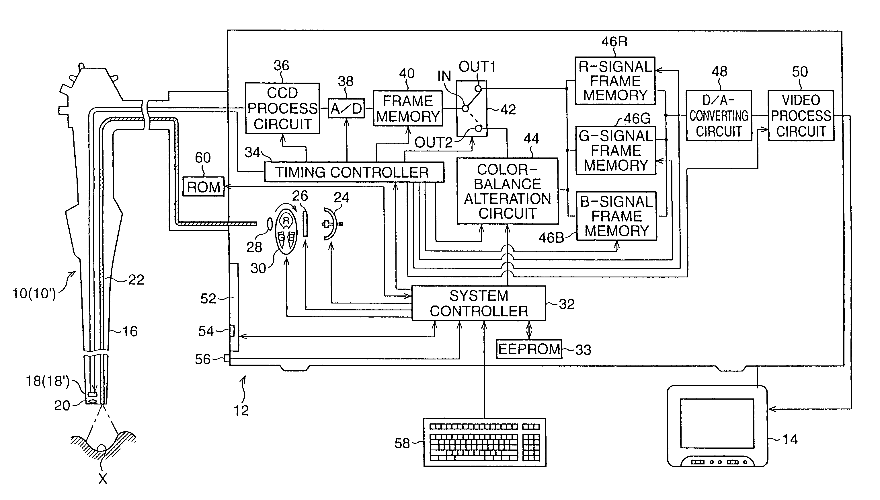
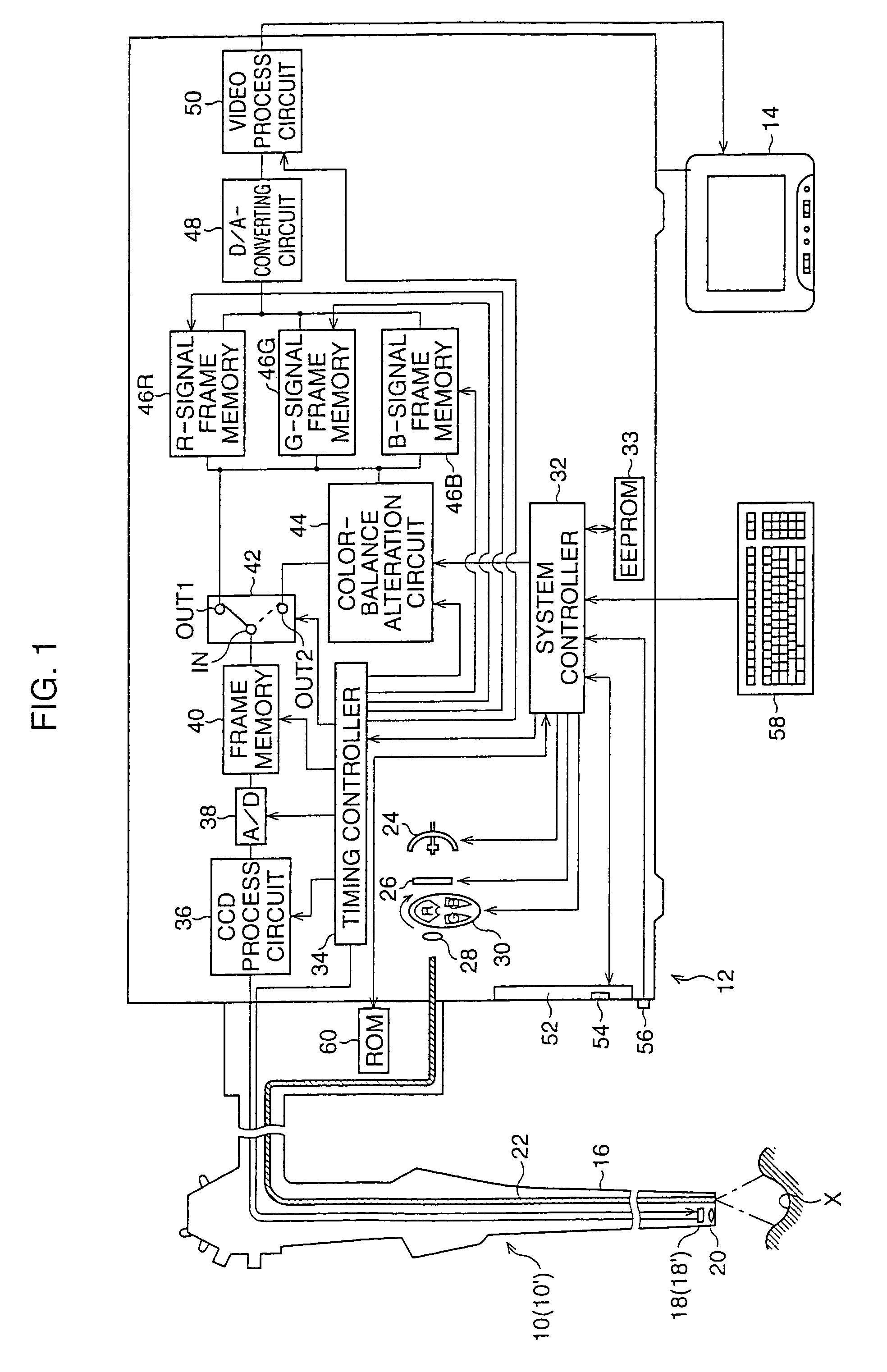
[0062]Referring to FIG. 1, a first embodiment of an electronic endoscope system according to the present invention is shown as a block diagram. The electronic endoscope system comprises a video scope 10, an image-signal processing unit 12 to which the video scope 10 is detachably coupled, and a TV monitor 14 to which the image-signal processing unit 12 is connected. In this embodiment, at least two video scopes 10 use the image-signal processor 12 in common. This is because the scope 10 is detachably coupled to the image-signal processing unit 12.

[0063]The video scope 10 includes a flexible conduit 16 which is provided with a solid-state image sensor 18, such as a CCD (charge-coupled-device) image sensor, at the distal end thereof, and the CCD image sensor 18 is associated with an objective lens 20. When a connection is established between the video scope 10 and the image-signal processing unit 12, the CCD image sensor 18 is electrically connected to an image-signal processor provid...

second embodiment

[0131]Referring to FIG. 8, a second embodiment of an electronic endoscope system according to the present invention is shown as a block diagram. In this drawing, the features similar to those of FIG. 1 are indicated by the same references.

[0132]In the second embodiment, an on-chip color filter method (i.e., a simultaneous imaging method) is introduced to reproduce an endoscope image as a full color image on a TV monitor 14, instead of the RGB field sequential-type color imaging method, and a video scope 10 and an image-signal processing unit 12 are modified so as to conform to the on-chip color filter method.

[0133]In particular, a CCD image sensor 18 has a complementary color filter (not shown) provided on a light-receiving surface thereof. Also, a light source device, provided in the image-signal processing unit 12, is formed by a white light lamp 24, a diaphragm 26, and a condenser lens 28. Namely, the rotary color-filter 30 is eliminated from the light source device. Thus, white ...

third embodiment

[0143]Referring to FIG. 10, a third embodiment of an electronic endoscope system according to the present invention is shown as a block diagram. As is apparent from this drawing, the third embodiment is generally identical to the first embodiment shown in FIG. 1. In FIG. 10, the features similar to those of FIG. 1 are indicated by the same references. According to the third embodiment, the electronic endoscope system is constituted such that a simulated-dye-sprayed endoscope image is displayed together with a usual full color endoscope image on a TV monitor 14 while selecting a simulated dye-spraying (SDS) display mode, but only the usual full color endoscope image is displayed on the TV monitor 14 while selecting the usual display mode, similar to the first embodiment.

[0144]As shown in FIG. 10, in the third embodiment, a frame memory circuit 46 is substituted for the R-signal, G-signal, and B-signal frame memory 46R, 46G, and 46B, and includes a first R-signal frame memory 46R1, a ...


PUM


Abstract

In an electronic endoscope system including a video scope having a solid-state image sensor that successively produces a frame of red, green, and blue image-pixel signals, a difference value is calculated between a value of each of corresponding central red, green, and blue image-pixel signals and an average of values of circumferential image-pixel signals surrounding the central image-pixel signal. When the respective values of the central red and green image-pixel signals are smaller than the corresponding averages of values, they are decreased in proportion to the absolute values of the corresponding difference values. When the value of the central blue image-pixel signal is smaller than the corresponding average of values, it is increased in proportion to the absolute value of the corresponding difference value.

Description

BACKGROUND OF THE INVENTION[0001]1. Field of the Invention[0002]The present invention relates to an electronic endoscope system in which an endoscope image is reproduced as a full color image on a TV monitor, and, in particular, to such an electronic endoscope system with a color-balance alteration process, which is constituted such that, for example, the endoscope image can be reproduced on the TV monitor as if it were sprayed with a dye-solution.[0003]2. Description of the Related Art[0004]As is well known, an electronic endoscope system includes a video scope that is inserted in an organ of a human body, and the video scope has a solid-state image sensor for capturing an organ image or endoscope image as a frame of image-pixel-signals. Also, the electronic endoscope system also includes an image-signal processing unit for producing a video signal based on the frames of image-pixel-signals successively read from the solid-state image sensor, and a TV monitor for reproducing the en...

Claims


Application Information

Patent Timeline
Patent Type & Authority Patents(United States)
IPC IPC(8): H04N9/47H04N13/00H04N7/18A61B1/045H04N9/73
CPCH04N9/735A61B1/045H04N23/88
Inventor OZAWA, RYO
Owner HOYA CORP
Why Eureka
Try Eureka