Power converter control for automatic maximum power point tracking

a technology of power converters and control circuits, applied in the direction of instruments, instruments for comonautical navigation, optical radiation measurement, etc., can solve the problems of control system, control system loss, and inability to make out a lighting chang

Inactive Publication Date: 2006-05-30
CENT NAT DE LA RECHERCHE SCI
View PDF5 Cites 248 Cited by
  • Summary
  • Abstract
  • Description
  • Claims
  • Application Information

AI Technical Summary

Benefits of technology

[0024]The present invention more specifically aims at optimizing the converter output without adversely affecting its response speed.

Problems solved by technology

However, the control system shown in FIG. 1 cannot make out a lighting change from an abrupt variation of the load connected at the converter output or from a mere variation around the maximum power point of curve P=f(V) on which stands its operating point.
The control system is then lost and may even find itself in a steady state no longer corresponding to the maximum power point.
The same problem is posed in the case of an abrupt variation in the supplied load.
However, this adversely affects the output because of the significant generated oscillations.
A disadvantage of such a solution is that it considerably slows down the control by the lighting of the photovoltaic panel or by the abrupt variations of any power source connected upstream of the system.
Further, the differentiation between a maximum power point change (curve change) and a normal variation also poses a problem in terms of detection duration and reliability.
A lighting change at time t1 causes a reference loss for the control system.
However, the greater the oscillations, the more adversely this affects the system output.
Problems of system convergence after maximum power point changes are posed especially in case of a variable power source.
However, even if the input power source is stable a priori as should be the case, for example, for photovoltaic panels used in space (without clouds), such convergence problems may be encountered.
Indeed, space infrastructures having more and more complex geometries, shadow areas due to the very structure of satellites may appear.
Further, sensors may be partially damaged by dust impact, which leads to the same result.
A digital system however remains slow to isolate a drift from a normal operating variation.
Another disadvantage of a digital circuit is that it is in practice limited to frequencies of pulse trains for controlling switch 2 of some hundred kHz.

Method used


Image

  • Power converter control for automatic maximum power point tracking
  • Power converter control for automatic maximum power point tracking
  • Power converter control for automatic maximum power point tracking

Examples


Embodiment Construction

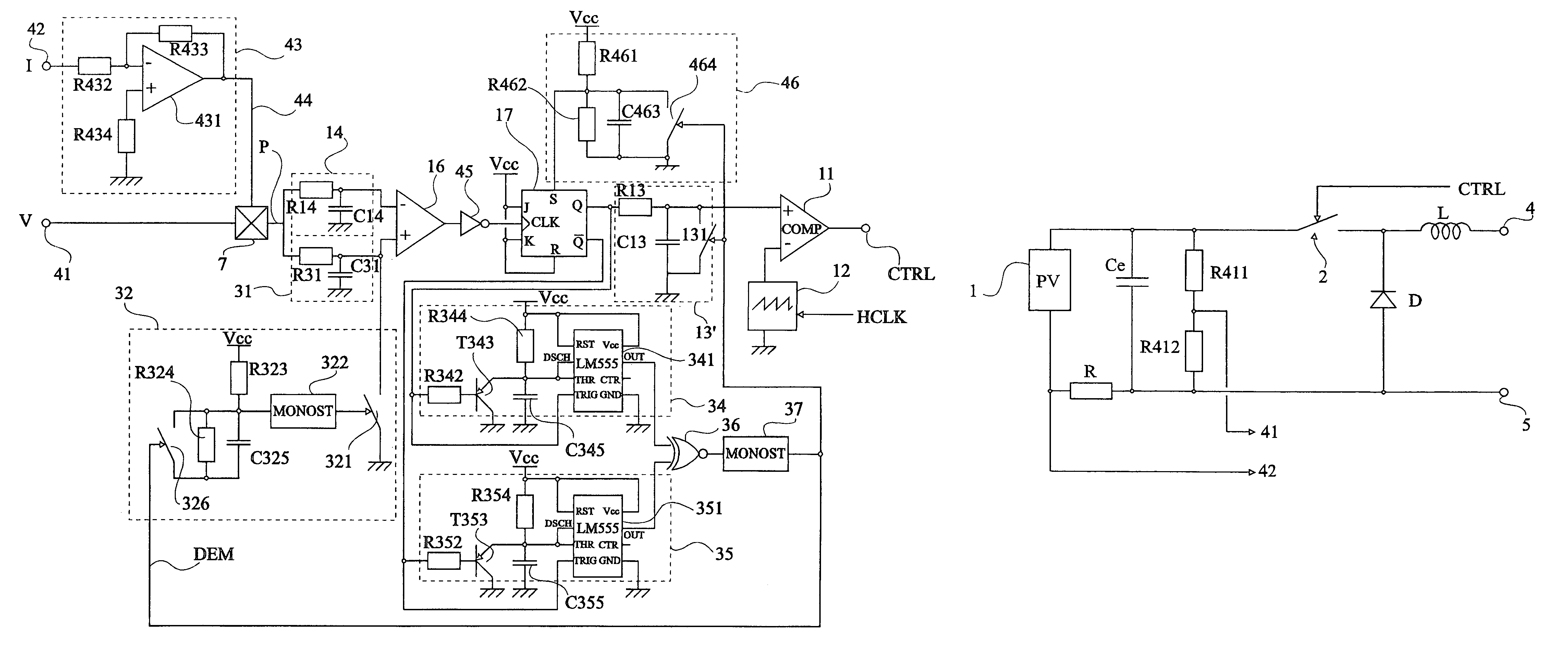
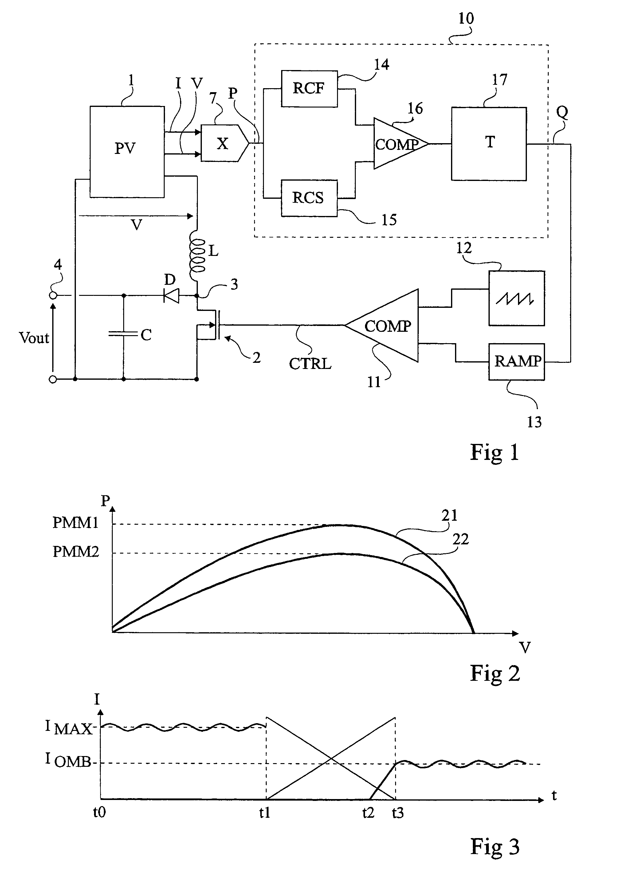
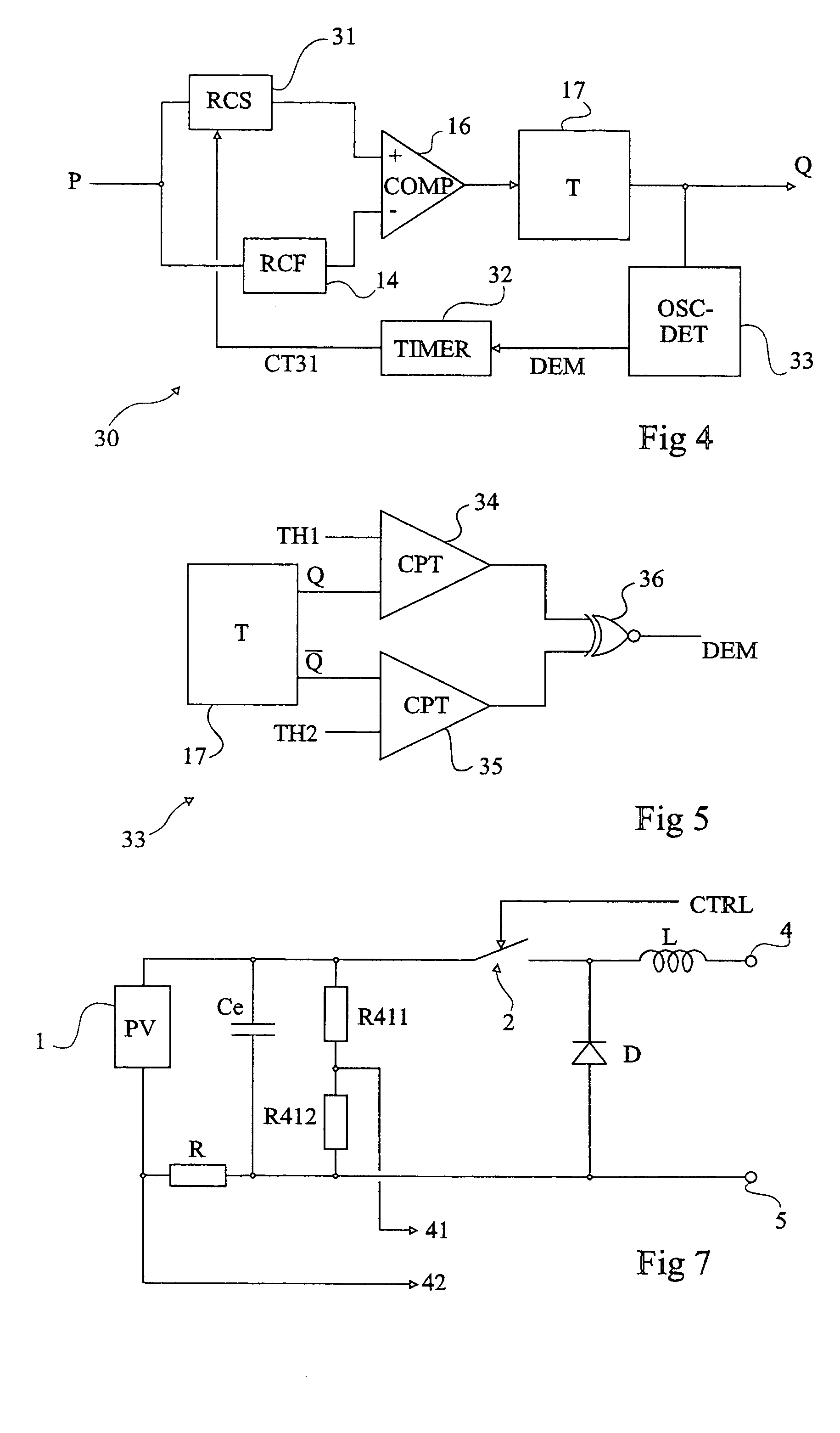
[0050]Same elements have been designated with same reference numerals in the different drawings. For clarity, only those elements which are necessary to the understanding of the present invention have been shown in the drawings and will be described hereafter. In particular, the forming of a power source exploited by a converter of the present invention has not been detailed and is no object of the present invention.

[0051]A feature of the present invention is to make one of the two delay elements exploiting the power information provided by the power source controllable. Advantage is then fully taken of the different functions of the respective time constants of the delay elements. Indeed, the slower delay element brings stability to the system while the faster delay element accelerates the convergence towards the maximum power point in case of a drift. Accordingly, by making the slower delay element faster or, preferably, by inhibiting it during a transient state corresponding to s...


PUM


Abstract

The invention concerns a method and a circuit for maximum power point tracking of a variable power source from a comparison of an image of the power (P) supplied by the power source, the circuit comprising two elements (14, 31) providing different propagating delays to a physical quantity proportional to the power image, a comparator (16) of the outputs of the delaying elements to control a trigger (17) supplying a signal (Q) with two automatic control states to a static power converter, and means (33) for detecting a transitory operating condition from variations in oscillations of an established operating condition and means (32) for modifying the delay input by the slower delaying element (31).

Description

PRIORITY FILING[0001]This application claims priority of the earlier filing date, under 35 U.S.C. 119, of the commonly owned PCT-based patent application, filing number PCT / FR02 / 00166, filed on Jan. 16, 2002, which claims priority of French Application No. 10 / 00517 filed on Jan. 16, 2001.BACKGROUND OF THE INVENTION[0002]1. Field of the Invention[0003]The present invention relates to the field of power converters and, more specifically, power converters equipped with a maximum power point tracking control circuit. Such converters are generally applied to the conversion of power provided by an irregular source. In the context of the present invention, “irregular” power source means a power source providing a power likely to undergo abrupt variations, as opposed to power sources providing a stable or slowly-varying power, as is the case for a battery or for the A.C. supply network. Such sources are, for example, photovoltaic panels providing a power varying according to the lighting, w...

Claims


Application Information

Patent Timeline
Patent Type & Authority Patents(United States)
IPC IPC(8): H01H35/00H02M3/155G05F1/67
CPCG05F1/67
Inventor ALONSO, CORRINESHRAIF, MOHAMED-FIRASMARTINEZ, AUGUSTIN
Owner CENT NAT DE LA RECHERCHE SCI
Why Eureka
Try Eureka