Shape variable mirror
a mirror and variable mirror technology, applied in the direction of instruments, optical elements, discharge tubes/lamp details, etc., can solve the problems of preventing abnormal deformation of the elastic member, and reducing the impact resistance of the micromachine element. , to achieve the effect of reducing the stress generated inside the elastic member, avoiding abnormal deformation of the elastic member, and avoiding deterioration of the impact resistan
- Summary
- Abstract
- Description
- Claims
- Application Information
AI Technical Summary
Benefits of technology
Problems solved by technology
Method used
Image
Examples
first embodiment
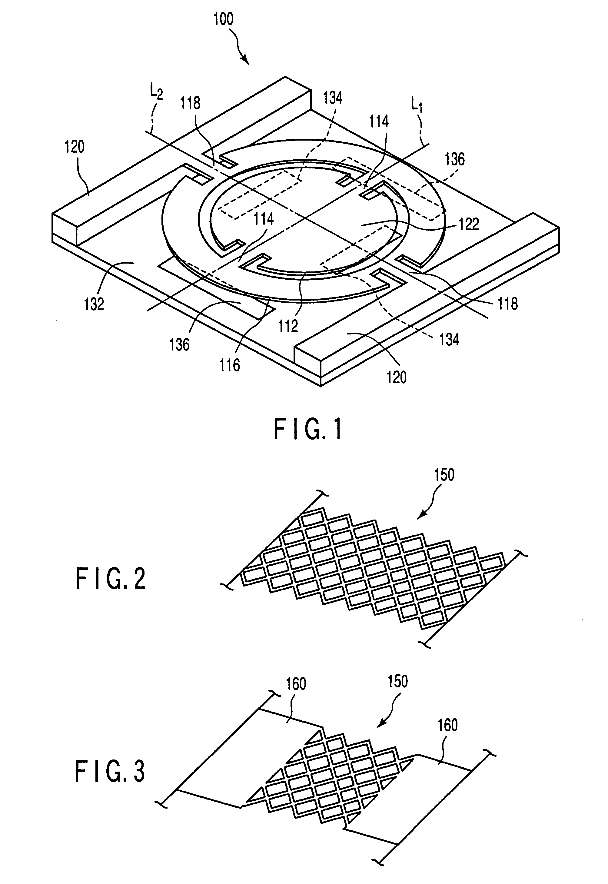
[0046]As a first embodiment of the present invention, FIG. 1 shows an optical deflection element having a movable structure according to the present invention.
[0047]The optical deflection element comprises a movable structure and a substrate 132 supporting the movable structure. The movable structure comprises an inner movable plate 112, an outer movable plate 116 corresponding the inner movable plate 112, a pair of torsion springs 114 connecting the inner movable plate 112 and the outer movable plate 116, a pair of supports 120 positioned outside the outer movable plate 116, and a pair of torsion springs 118 connecting the outer movable plate 116 and the supports 120.
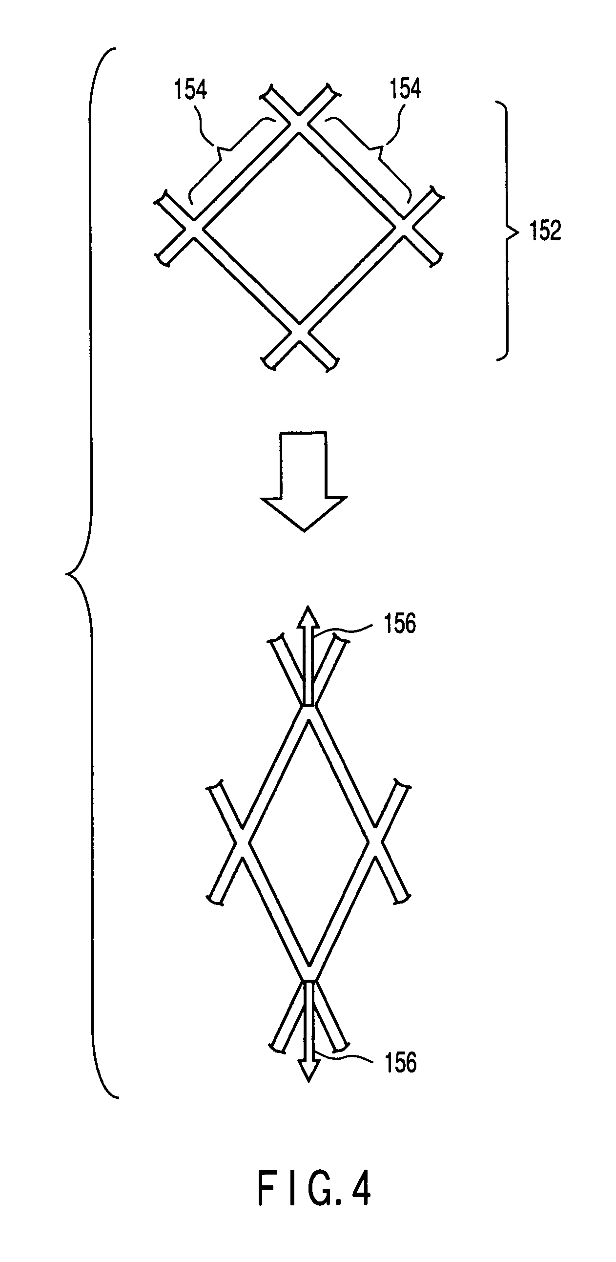
[0048]Both the inner torsion spring 114 and the outer torsion spring 118 at least partially have the mesh structure. For example, as shown in FIG. 2, the inner torsion spring 114 and the outer torsion spring 118 are entirely constituted by the mesh structure 150. Alternatively, as shown in FIG. 3, the inner torsion spr...
second embodiment
[0066]As a second embodiment according to the present invention, FIG. 6 shows an optical switch element having a movable structure according to the present invention.
[0067]The optical switch element 200 comprises a movable structure and a substrate 232 supporting the movable structure. The movable structure comprises a rectangular movable plate 212, four supports 216 positioned around the movable plate 212 with respect to each side of the movable plate 212, and four support springs 214 connecting each side of the movable plate 212 and each of the supports 216.
[0068]The support spring 214 at least partially has a mesh structure. For example, as shown in FIG. 2, the support spring is entirely constituted by the mesh structure 150. Alternatively, as shown in FIG. 3, the support spring 214 partially has the mesh structure 150. That is, the support spring 214 has the mesh structure 150 and the platy portion 160.
[0069]The movable plate 212 is allowed to move so as to be closer to the subs...
third embodiment
[0082]As a third embodiment according to the present invention, FIG. 7 shows a shape variable mirror having the movable structure according to the present invention.
[0083]The shape variable mirror 300 includes a movable structure and a substrate 332 supporting the movable structure. The movable structure comprises a deformable elastic film 312 having a reflection surface, a pair of supports 316 positioned on the both sides of the elastic film 312, and a pair of support springs 314 connecting the elastic film 312 and the support 316.
[0084]The support springs 314 at least partially have the mesh structure. For example, as shown in FIG. 2, each of the support spring 314 is entirely constituted by the mesh structure 150. Alternatively, as shown in FIG. 3, the support spring 314 partially has the mesh structure 150. That is, the support spring 314 has the mesh structure 150 and a platy portion 160.
[0085]The substrate 332 has electrodes 334 opposed to the elastic film 312. A metal film 31...
PUM
 Abstract
Description
Claims
Application Information
 - R&D
- Intellectual Property
- Life Sciences
- Materials
- Tech Scout
- Unparalleled Data Quality
- Higher Quality Content
- 60% Fewer Hallucinations
Browse by: Latest US Patents, China's latest patents, Technical Efficacy Thesaurus, Application Domain, Technology Topic, Popular Technical Reports.
© 2025 PatSnap. All rights reserved.Legal|Privacy policy|Modern Slavery Act Transparency Statement|Sitemap|About US| Contact US: help@patsnap.com


