

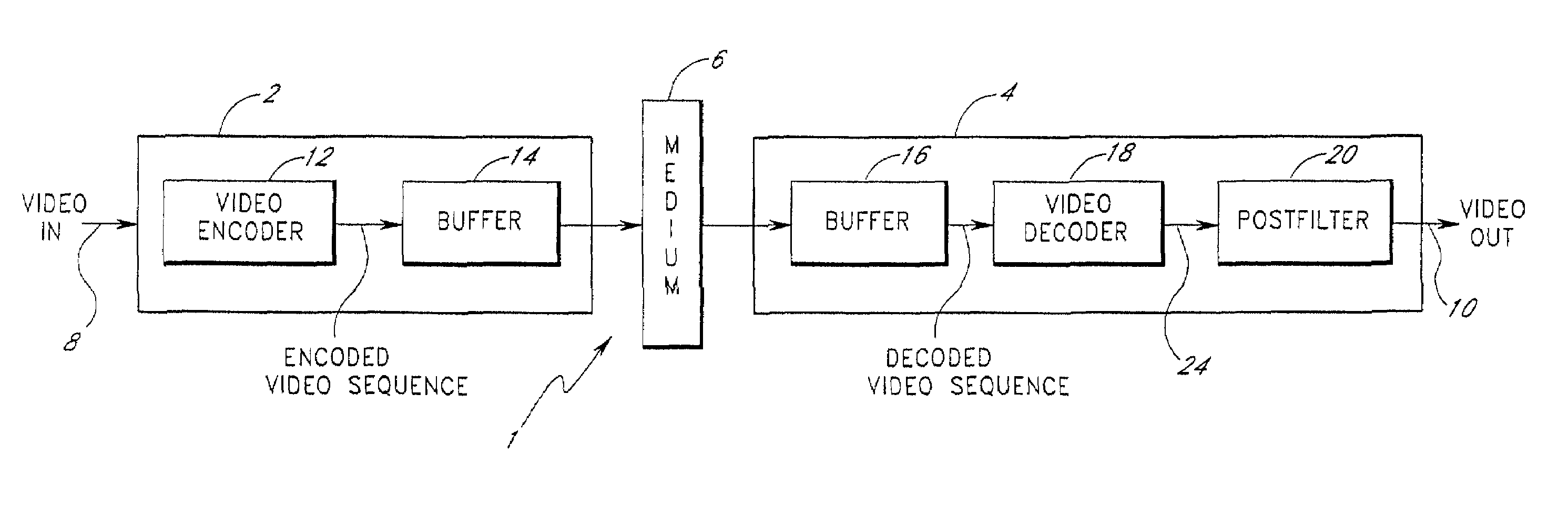
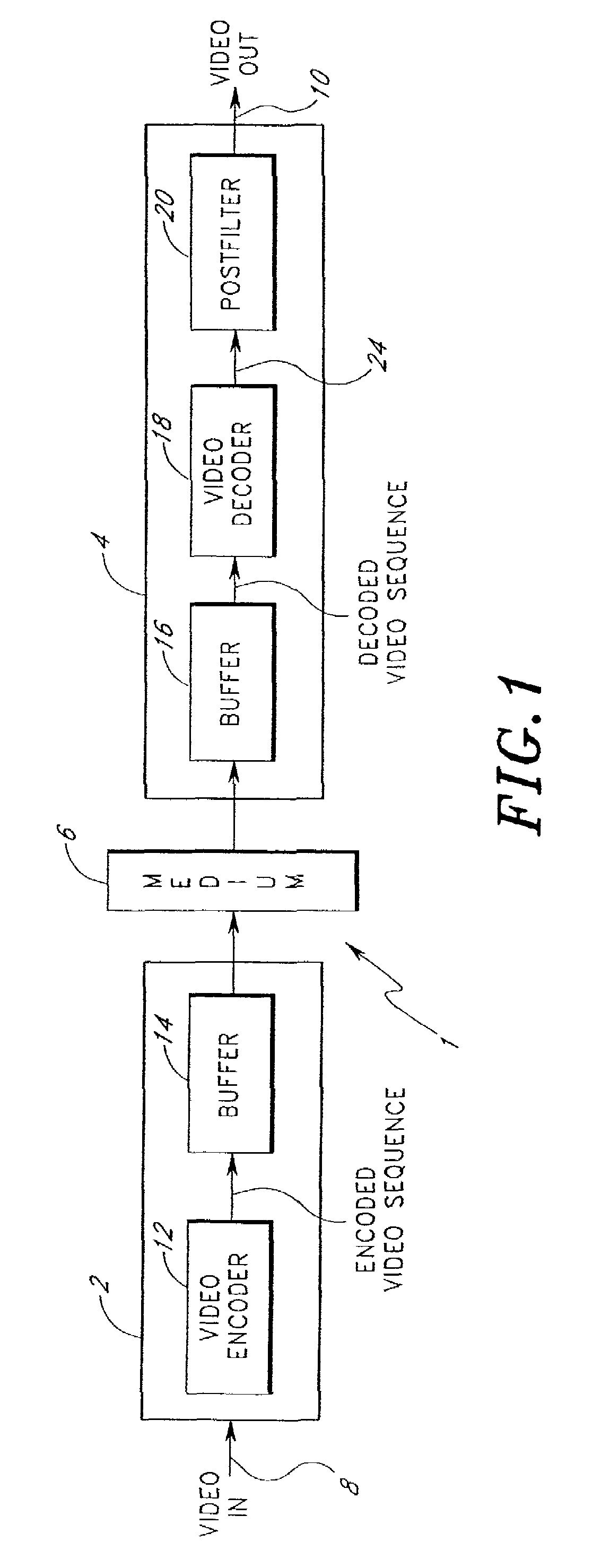
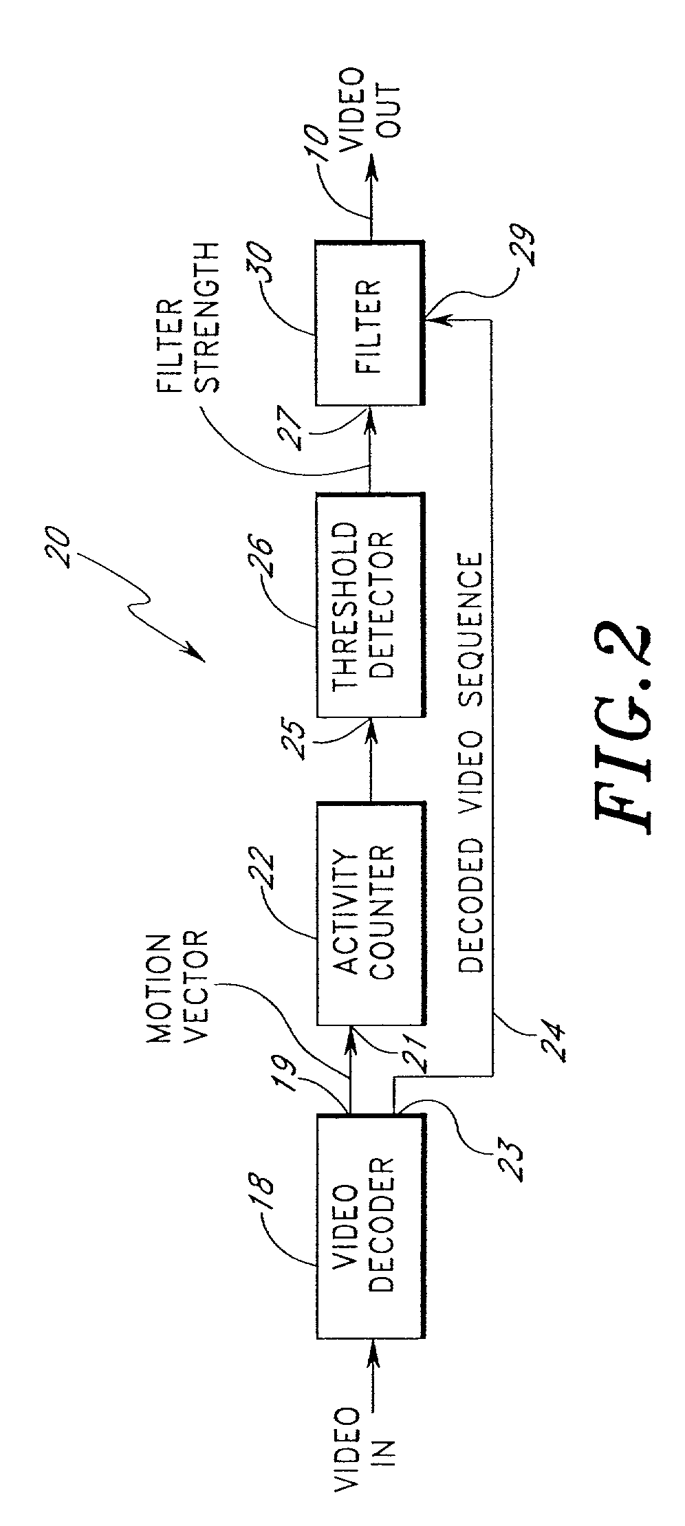
Video compression and decompression system with postfilter to filter coding artifacts
a video compression and decompression system technology, applied in the field of video compression and decompression systems, can solve the problems of inability to detect the boundaries between moving objects and stationary backgrounds that fall within these blocks, the size of the quantization steps needs to be relatively large, and the visual quality of the decoded sequence that may be displayed
- Summary
- Abstract
- Description
- Claims
- Application Information
AI Technical Summary
Benefits of technology
Problems solved by technology
Method used
Image

Examples
Embodiment Construction
[0021]In the following description, reference is made to the accompanying drawings, which form a part hereof, and which show, by way of illustration, specific embodiments in which the invention may be practiced. It is to be understood that other embodiments may be utilized and structural changes may be made without departing from the scope of the present invention. Where possible, the same reference numbers will be used throughout the drawings to refer to the same or like components. Numerous specific details are set forth in order to provide a thorough understanding of the present invention. However, it will be obvious to one skilled in the art that the present invention may be practiced without the specific details or with certain alternative equivalent devices and methods to those described herein. In other instances, well-known methods, procedures, components, and devices have not been described in detail so as not to unnecessarily obscure aspects of the present invention.
[0022]...
PUM
 Abstract
Description
Claims
Application Information