Method of coding artifacts reduction

a technology of artifacts and coding, applied in the field of coding arefacts reduction, can solve the problems of only noticable image improvement, all the above described methods inherit the disadvantage of a relatively high needed calculation power, etc., and achieve the effect of minimizing the required filter operation

Inactive Publication Date: 2008-04-01
SONY DEUT GMBH
View PDF24 Cites 8 Cited by
  • Summary
  • Abstract
  • Description
  • Claims
  • Application Information

AI Technical Summary

Benefits of technology

[0016]In any case, according to the present invention artefacts are removed by improving the subjective picture quality and therefore keeping as much picture details as possible. This also leads to a decreased calculation power needed for the filtering and determination of the filter functions.
[0031]Therefore, the present invention exploits the behaviour that a high subjective image quality value indicates a low level of coding artefacts and a low subjective image quality value indicates a high level of coding artefacts. Therefore, the subjective image quality value is used to choose a filter from a set of filters with several characteristics. The chosen filter is applied in the relevant regions for the type of artefacts, e.g. at block borders to process in case of blocking, or inside the block to process ringing, or at every pixel position between two pictures in case of temporal filtering. The method according to the present invention enables to pass frames without filtering that have been encoded with high quality and to smooth frames that have been encoded with poor quality. The degree of smoothing is controlled by the image quality value.

Problems solved by technology

However, all of the above described methods inherit the disadvantage of a relatively high needed calculation power because of processing an entire image and in particular to determine a filtering characteristic in the aim to reduce coding artefacts based upon determination of an objective parameter influencing the respective filtering.
Further, the image improvement is only noticable by encoding with a relatively low bit rate.

Method used


Image

  • Method of coding artifacts reduction
  • Method of coding artifacts reduction
  • Method of coding artifacts reduction

Examples


Embodiment Construction

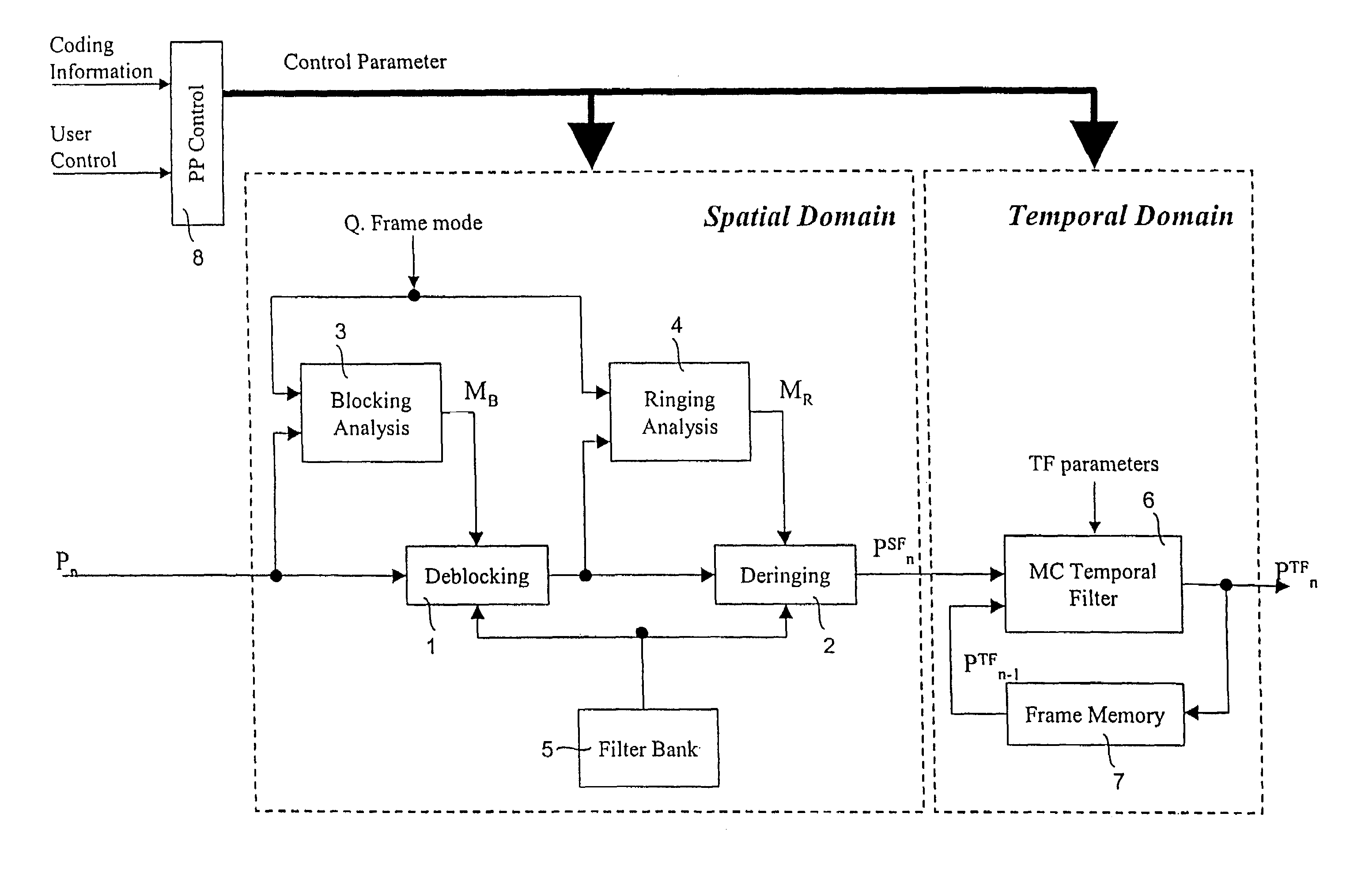
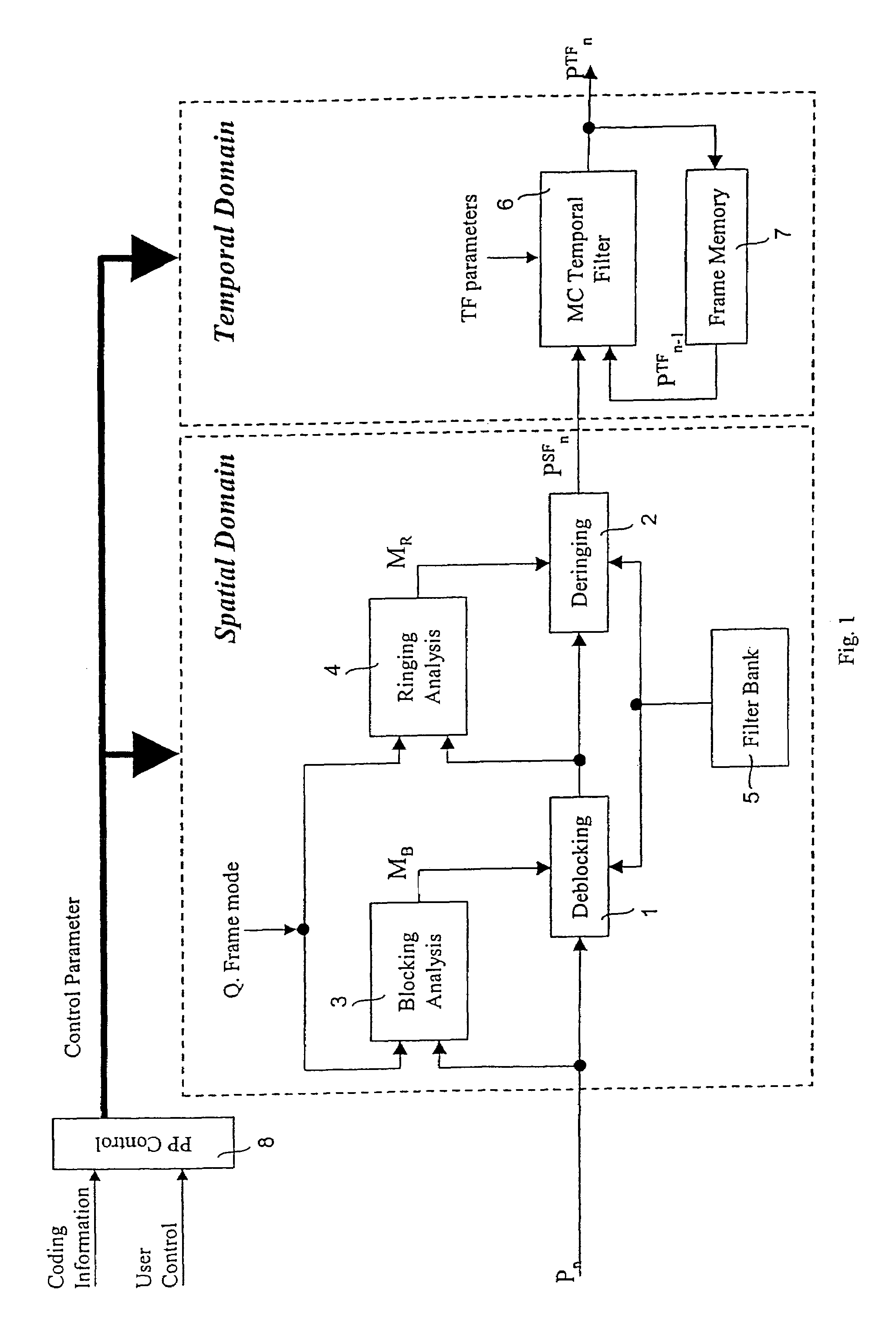
[0044]FIG. 1 shows a preferred embodiment of a system to reduce coding artefacts in conformity with the method to reduce coding artefacts within a discrete decoded picture according to the present invention. An incoming picture signal Pn first undergoes a deblocking filtering 1 with a following deringing filtering 2 in the spatial domain before it is filtered in the temporal domain by a motion compensation temporal filter 6 which outputs the coding artefacts reduced picture signal pTFn. The deblocking filter 1 and the deringing filter 2 have both access to a filter bank 5 to perform the respective necessary filter operations. To decide which parts of the picture will be subjected to the deblocking filtering 1 and the deringing filtering 2 a respective analysis is performed as described above. Therefore, a blocking analysis block 3 receives the incoming picture signal Pn to output a control signal MB for the deblocking filter 1 and a ringing analysis block 4 receives the output signa...


PUM


Abstract

A method to reduce coding artifacts within a discrete decoded picture includes a spatial and / or temporal filtering with respective filter characteristics dependent on an image quality value (Q). Preferably, the spatial filtering includes a deblocking filtering, wherein the deblocking filter operation decreases with an increasing image quality value (Q) and / or the deblocking filtering chooses an image quality value (Q) dependent weighting function for a pixel to be filtered according to an activity of both blocks to which common border said pixel belongs.

Description

BACKGROUND OF THE INVENTION[0001]1. Field of the Invention[0002]The present invention is generally related to a method of coding arefacts reduction, in particular of a discrete decoded picture.[0003]Generally, picture coding / compression standards like JPEG or MPEG are based on block-based discrete cosine transformation (DCT) encoding. Therefore, a loss of quality might arise within an encoded image, such as blocking or ringing artefacts.[0004]2. Description of Related Art[0005]Different methods are proposed to reduce such a loss of quality, like from H. W. Park, Y. L Lee “A Postprocessing Method For Reducing Quantization Effects And Low Bit-Rate Moving Picture Coding”, IEEE Transactions on Circuit Systems For Video Technology, Vol. 9, No. 1, February 1999, pages 161-171, and by S. Minami, A. Zakhor “An Optimization Approach for Removing Blocking Effects in Tranform Coding”, IEEE Transactions on Circuits and Systems for Video Technology, Vol 5, No. 2, April 1995, pages 74 to 82.[0006...

Claims


Application Information

Patent Timeline
Patent Type & Authority Patents(United States)
IPC IPC(8): G06K9/40G06T5/20G06T9/00H03M7/30H04N5/14H04N5/21H04N19/117H04N19/136H04N19/14H04N19/154H04N19/16H04N19/162H04N19/169H04N19/17H04N19/172H04N19/176H04N19/44H04N19/61H04N19/80H04N19/86
CPCH04N19/176H04N19/172H04N19/169H04N19/61H04N19/117H04N19/136H04N19/86H04N19/154H04N19/16H04N19/162H04N19/17H04N19/44H04N19/80H04N19/14
Inventor ESTEVEZ, MIGUELUNRUH, CHRISTIANWAGNER, PETER
Owner SONY DEUT GMBH
Why Eureka
Try Eureka