Vehicle side mirror assembly with rearward and forward viewing

Inactive Publication Date: 2006-06-06
MURAKAMI CORP
View PDF14 Cites 12 Cited by
  • Summary
  • Abstract
  • Description
  • Claims
  • Application Information

AI Technical Summary

Benefits of technology

[0030]In this outer mirror, the frame is secured to the mirror housing in two or more directions, thereby increasing the attached strength of the frame.

Problems solved by technology

This insertion process is time consuming and t

Method used


Image

  • Vehicle side mirror assembly with rearward and forward viewing
  • Vehicle side mirror assembly with rearward and forward viewing
  • Vehicle side mirror assembly with rearward and forward viewing

Examples


Example

First Embodiment

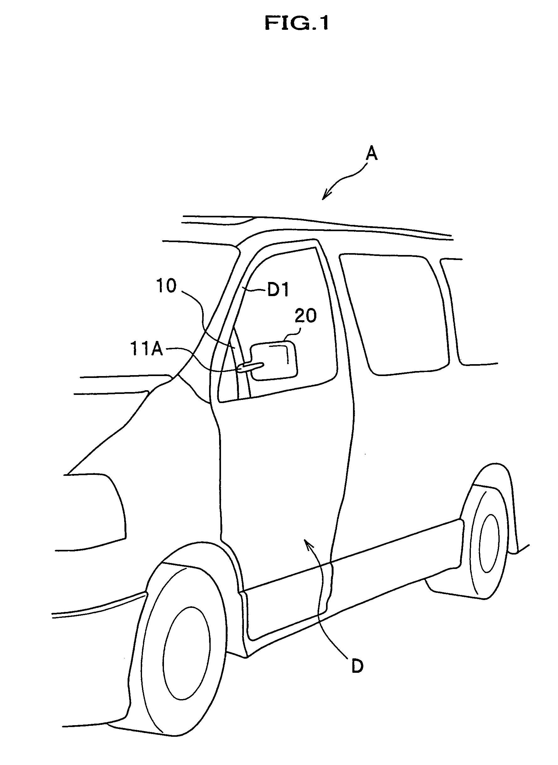
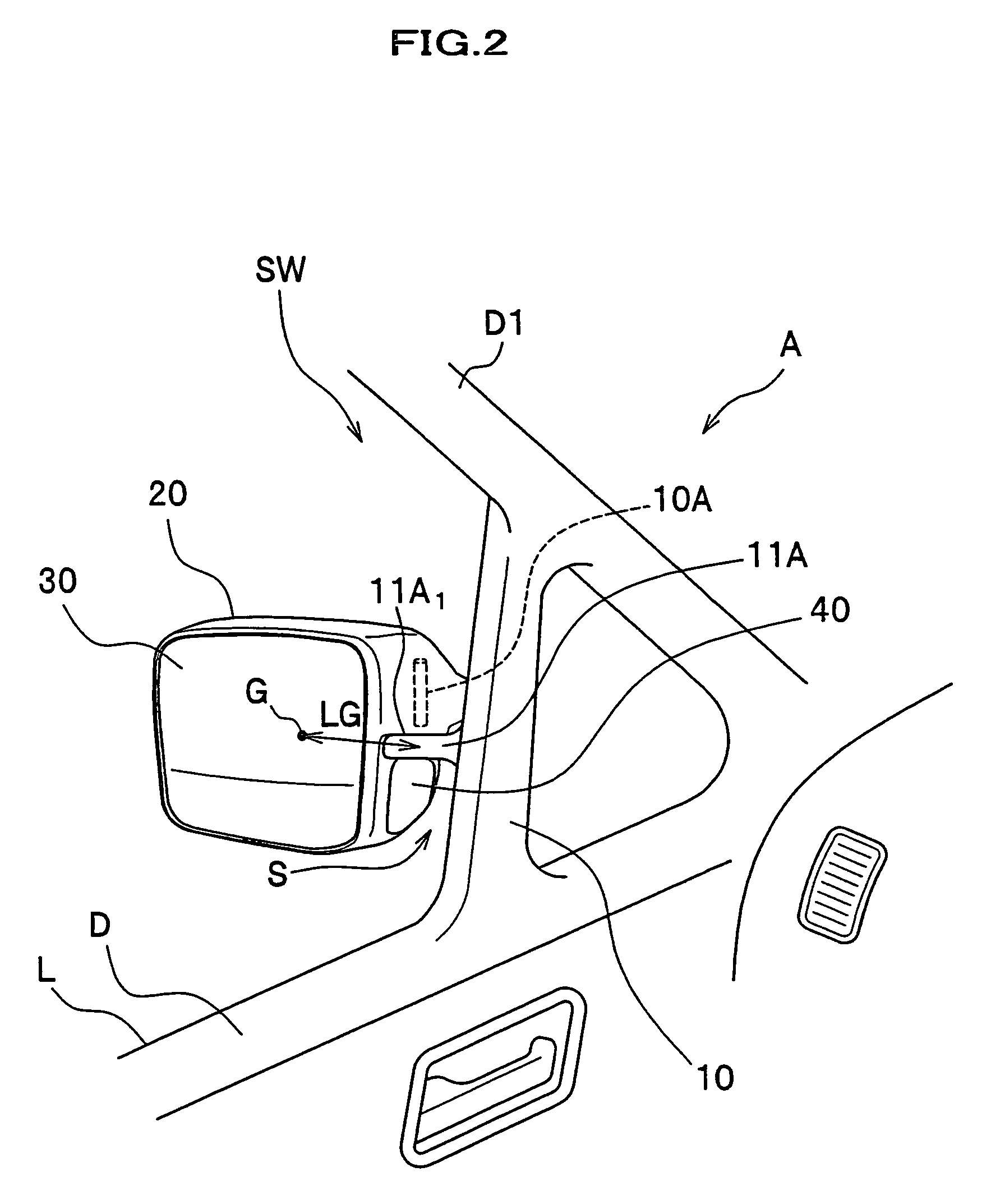
[0046]As shown in FIGS. 1 and 2, an outer mirror of this embodiment is what is called a door mirror, mounted on a front side door D on the passenger seat side of a vehicle body A. The outer mirror is composed of a mirror base 10 that has a protrusion 11A extending laterally from a side face of the vehicle body A, and a mirror housing 20 mounted on the upper side of the protrusion 11A. As shown in FIG. 2, a mirror 30 is provided on a rear face of the mirror housing 20, for viewing the rear area, and an auxiliary mirror 40 is provided on the vehicle body side surface of the mirror housing 20, for viewing an area diagonally forward the passenger seat of the vehicle body A, which is not seen directly from the driver seat.

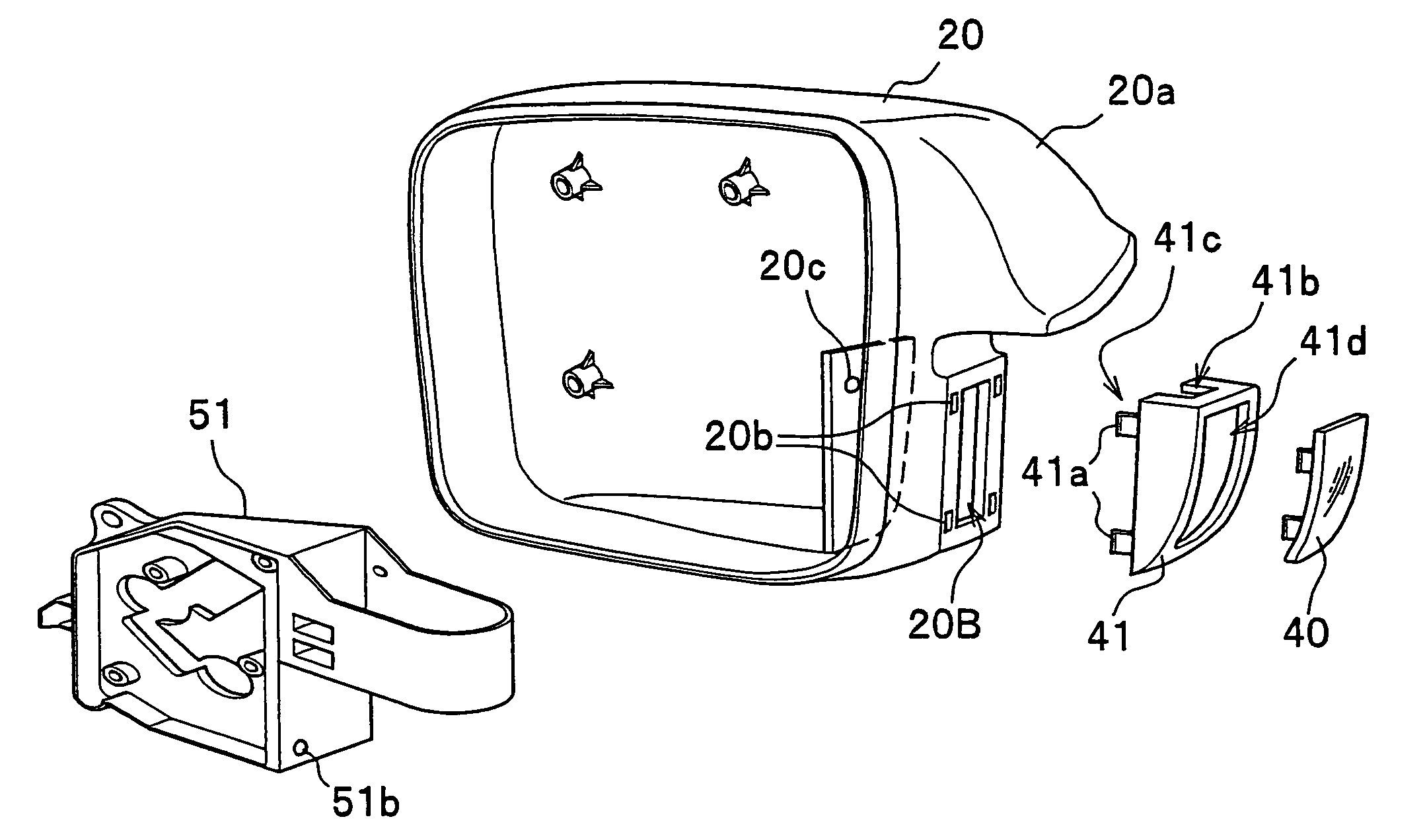
[0047]Referring to FIG. 3, the mirror housing 20 is provided with an opening 20B on its vehicle body side surface to which an auxiliary mirror 40 is to be attached.

[0048]In this embodiment, the outer mirror is an electrically-operated retractable mirror,...

Example

Second Embodiment

[0102]An outer mirror according to a second embodiment of the present invention is characterized in that an auxiliary rear view mirror 70 is introduced, as shown in FIGS. 9 and 10.

[0103]The auxiliary rear view mirror 70 is mounted on the mirror housing 60 at the position above the protrusion 11A (upper portion 60a on the side of the mirror housing 60). The mirror surface of the auxiliary rear view mirror 70 tilts down so as to face the ground. By introducing this auxiliary rear view mirror 70, the area around the rear side of the vehicle body A can be reflected.

[0104]According to this outer mirror, the area diagonally backward the side face of the vehicle body A can be checked by use of the auxiliary rear view mirror 70. When the auxiliary rear view mirror 70 is combined with the mirror 30 for viewing behind, the areas behind the vehicle body A, including those which in general cannot be seen from the driver seat, can be easily checked. In addition, since the auxili...


PUM


Abstract

Disclosed is an outer mirror in which individual components are easy to assemble and which is superior in durability. An outer mirror includes a mirror base having a protrusion which sticks out outward from a side face of a vehicle body, a shaft being placed on the protrusion, and a mirror housing being coupled to the shaft in a rotatable fashion. Furthermore, the mirror housing includes a mirror for showing an area behind the vehicle body, and an opening on its side that faces the vehicle body.

Description

CROSS-REFERENCE TO RELATED APPLICATIONS[0001]The present application claims priority under 35 U.S.C. §119 to Japanese Patent Application No. 2004-366846, filed Dec. 17, 2004, entitled “OUTER MIRROR”. The contents of that application are incorporated herein by reference in their entirety.BACKGROUND OF THE INVENTION[0002]1. Field of the Invention[0003]The present invention relates to an outer mirror to be attached to a side door of a vehicle or a surrounding area of the side door.[0004]2. Description of the Related Art[0005]Referring to FIG. 11, a typical outer mirror includes as main components:a) a mirror base 110 that has a ledge 100 protruding from the side of a vehicle body (not shown);b) a shaft 111 secured to the upper surface of the ledge 100;c) a mirror housing 113 mounted on the shaft 111 through a drive unit 112 in a rotatable fashion; and[0006]d) a mirror 115 fixed to an opening 113A formed on the rear of the mirror housing 113 through an actuator 114 for adjusting the ori...

Claims


Application Information

Patent Timeline
IPC IPC(8): G02B5/08B60R1/08B60R1/10
CPCB60R1/06B60R1/10B60R1/082B60R1/08
Inventor MATSUURA, MASAAKIMOTOMIYA, MASAHIROSUZUKI, HISAYA
Owner MURAKAMI CORP
Why Eureka
Try Eureka