Continuous pour concrete slip dowel

Inactive Publication Date: 2012-01-19
TDJ MASONRY
View PDF11 Cites 1 Cited by
  • Summary
  • Abstract
  • Description
  • Claims
  • Application Information

AI Technical Summary

Benefits of technology

[0027]A sliding mechanism is associated with the first rod end to provide a sliding relationship between the first rod end and the concrete slab on the first side of the joint. The sliding mechanism in one embodiment can take the form of a slip sleeve configured to be positioned within a first concrete slab wherein the first rod end portion configured to be slidingly received within the slip sleeve. The sliding mechanism in one embodiment can take the form of a relatively smooth exterior of the first rod end which is coated to prevent attachment of the concrete during setting. The coating may be tar, pitch, grease, petroleum gels or the like which prevent the setting concrete from attaching to the first

Problems solved by technology

While a control joint protects the concrete slab from damage due to contraction of the concrete during curing and expansion or contraction thereafter within the slab itself, the joints prohibit loads placed on the concrete slab to be transferred uniformly throughout.
As a result, control joints, without further reinforcement, leave the concrete slabs susceptible to damage.
For instance, loads developed by a forklift moving across a non-reinforced control joint poses a serious risk of damage to the slab because the forklift's load at the control joint is supported by only one half of the volume of concrete as available to support the forklift in an portion of the slab without a control joint.
The non-parallel positioning of the dowels will prevent the desired slippage of the dowels and will defeat the purpose of the “slip dowel” application.
Although the above described “drilling method” of placing slip dowe

Method used


Image

  • Continuous pour concrete slip dowel
  • Continuous pour concrete slip dowel
  • Continuous pour concrete slip dowel

Examples


Example

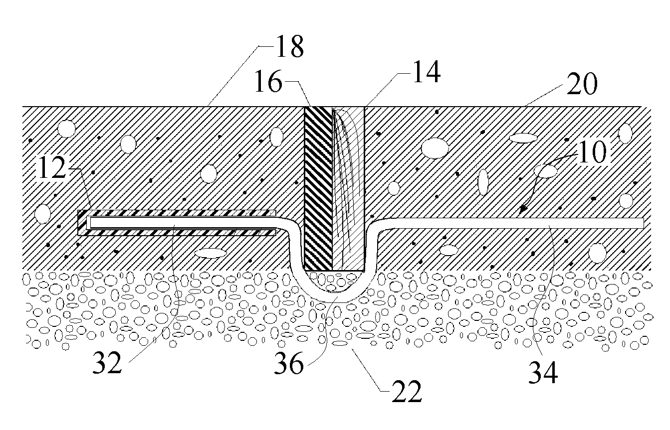
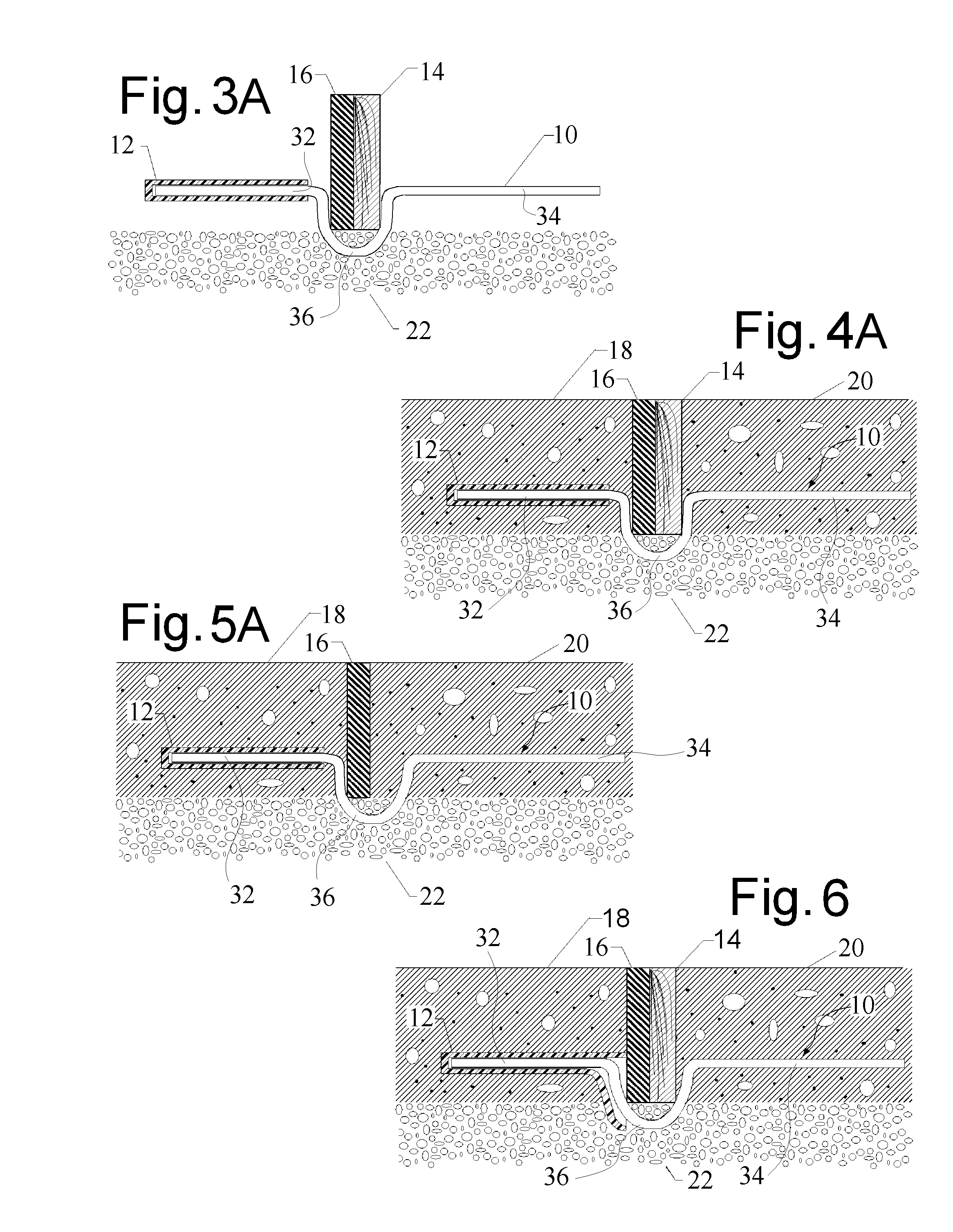
[0043]In summary, the present invention relates to a continuous pour concrete slip dowel 10 which is disclosed configured for use across a joint, such as an expansion joint having an expansion member 16 between adjacent concrete slabs 18 and 20. The construction of the expansion member 16 is known in the art, but generally is formed of a rubber or other elastomeric material, or a composite of several materials, and configured to accommodate slab expansion and withstand the operating environment.

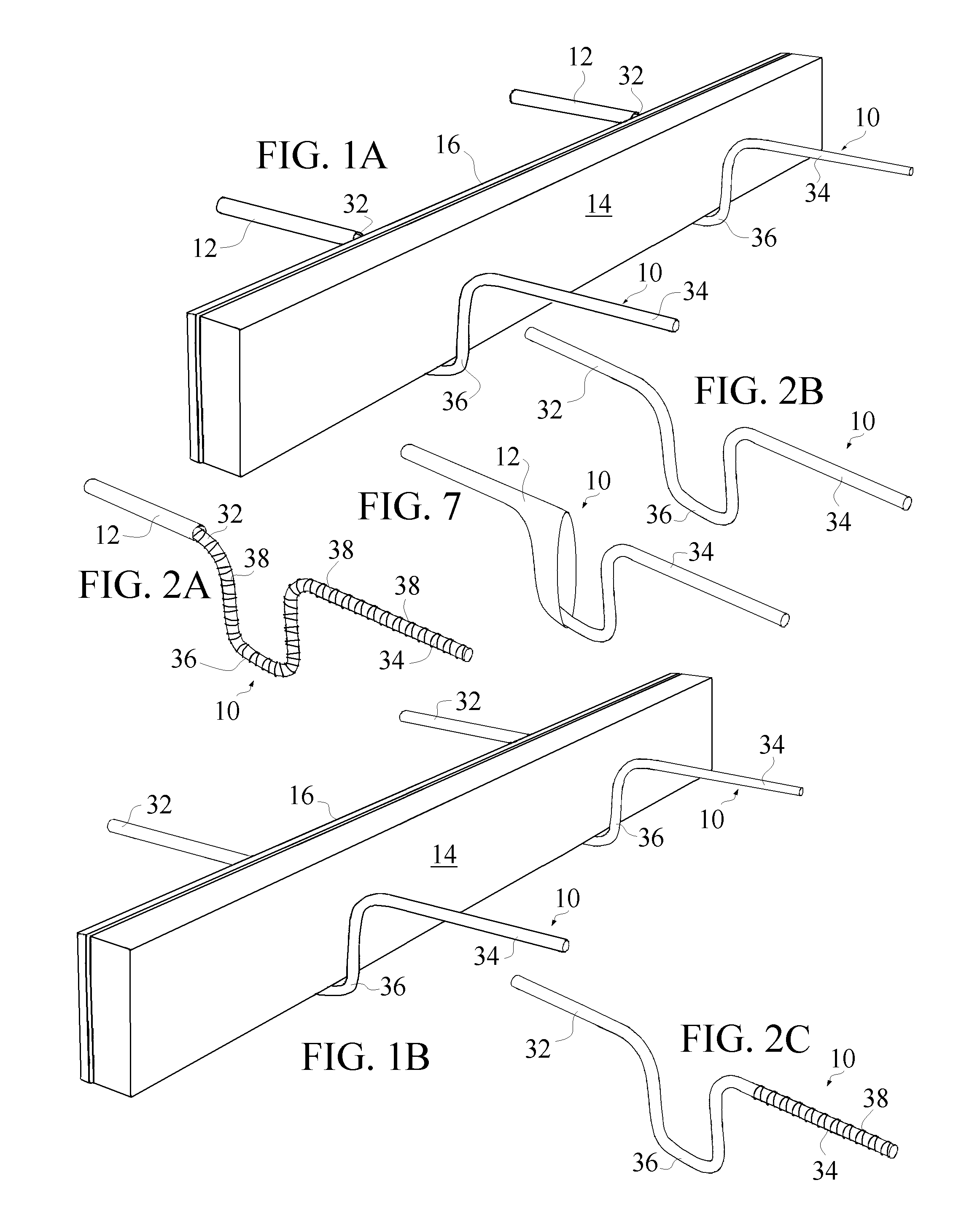
[0044]The continuous pour concrete slip dowel 10 of the invention includes a sliding mechanism that is associated with, at least, a first rod end 32 of the dowel 10 to provide a sliding relationship between the first rod end 32 and the concrete slab 18 on the first side of the joint formed by member 16.

[0045]In one embodiment of the present invention shown in FIGS. 1A, 2A, 3A, 4A, 5A, 6 and 7, the sliding mechanism is formed by a slip sleeve 12 configured to be positioned within the first con...


PUM


Abstract

According to one non-limiting embodiment of the present invention, a continuous pour concrete slip dowel is disclosed configured for use across a joint between adjacent concrete slabs. The continuous pour concrete slip dowel of the invention includes a slip sleeve configured to be positioned within a first concrete slab, and a main dowel rod having i) a first rod end portion configured to be received within the slip sleeve, ii) a second opposed rod end configured to be received within a second concrete slab which is adjacent the first slab and spaced from the first slab by a intervening joint, and iii) an intermediate coupling rod portion connecting the first rod end with the second rod end, wherein the coupling rod portion defines an offset therein whereby the coupling rod portion is configured to extend around the joint.

Description

RELATED APPLICATIONS[0001]The present invention claims priority of U.S. Provisional Patent Application Ser. No. 61 / 292,658 entitled “Continuous Pour Concrete Slip Dowel” filed Jan. 6, 2010.BACKGROUND OF THE INVENTION[0002]1. Field of the Invention[0003]The present invention relates to concrete construction and more particularly, the present invention is directed to a concrete slip dowel which allows for continuous pours.[0004]2. Background Information[0005]U.S. Pat. Nos. 2,152,751; 3,437,018; 4,578,916; 4,733,513; 4,959,940; 5,005,331; 5,216,862; 5,487,249; 5,678,952; 5,797,231; 5,934,821; 6,502,359 provide, collectively, a meaningful background discussion in this field noting that in the art of concrete construction, it is commonplace to form joints between two or more poured concrete slabs allowing for thermal expansion of each slab. This type of joint is called an expansion joint. An expansion joint is formed by the placement of compressible materials consisting typically of wood...

Claims


Application Information

Patent Timeline
IPC IPC(8): E04B1/68
CPCE04B1/483
Inventor MCCORKLE, DALE
Owner TDJ MASONRY
Why Eureka
Try Eureka