
Transmission for distributing a drive torque

Inactive Publication Date: 2006-06-06
ZF FRIEDRICHSHAFEN AG
View PDF15 Cites 41 Cited by
  • Summary
  • Abstract
  • Description
  • Claims
  • Application Information

AI Technical Summary

Benefits of technology

[0013]With the inventive transmission for distributing a drive torque to at least two output shafts having at least two planetary gear sets with at least three shafts, a starting off is ensured, even in critical driving situations like on slippery soil, with simple constructional means and at low technical control and regulation expenses.
[0014]This is achieved by the fact that when a rotational speed difference exists between two operatively interconnected shafts of the planetary gear sets, one torque that reduces the rotational speed difference between two output shafts of the planetary gear sets abuts on the planetary gear sets.
[0015]If the inventive transmission is used as differential transmission for transverse distribution of a drive torque to the two drive wheels of a drive vehicle axle, the two drive wheels are each connected with one output shaft of a planetary gear set. This results in a spinning of a drive wheel, which moves along with a rotational speed difference between both output shafts, and is counteracted in the sense that the spinning output shaft is braked via the operative connection between the two operatively interconnected shafts and the other drive wheel is loaded via the second output shaft of the transmission at least with part of the drive torque whereby a starting off of the vehicle is advantageously made possible.

Problems solved by technology

However, opposed to these advantages is the disadvantage that the propulsion forces of two drive wheels of a vehicle axle or of two or more drive axles transmissible to the road, due to the compensating action of a differential transmission, depend on the slight or slightest transmissible drive torque of both drive wheels or of the drive axles.
In such a driving situation, the vehicle disadvantageously cannot start off due to the compensating action of a differential transmission which makes a rotational speed difference possible between two output shafts of a differential transmission.
The previously mentioned solutions, however, have the disadvantage of being characterized by high control and regulation costs and besides require high constructional expenses due to the hydraulic system.

Method used


Image

  • Transmission for distributing a drive torque
  • Transmission for distributing a drive torque
  • Transmission for distributing a drive torque

Examples


Embodiment Construction

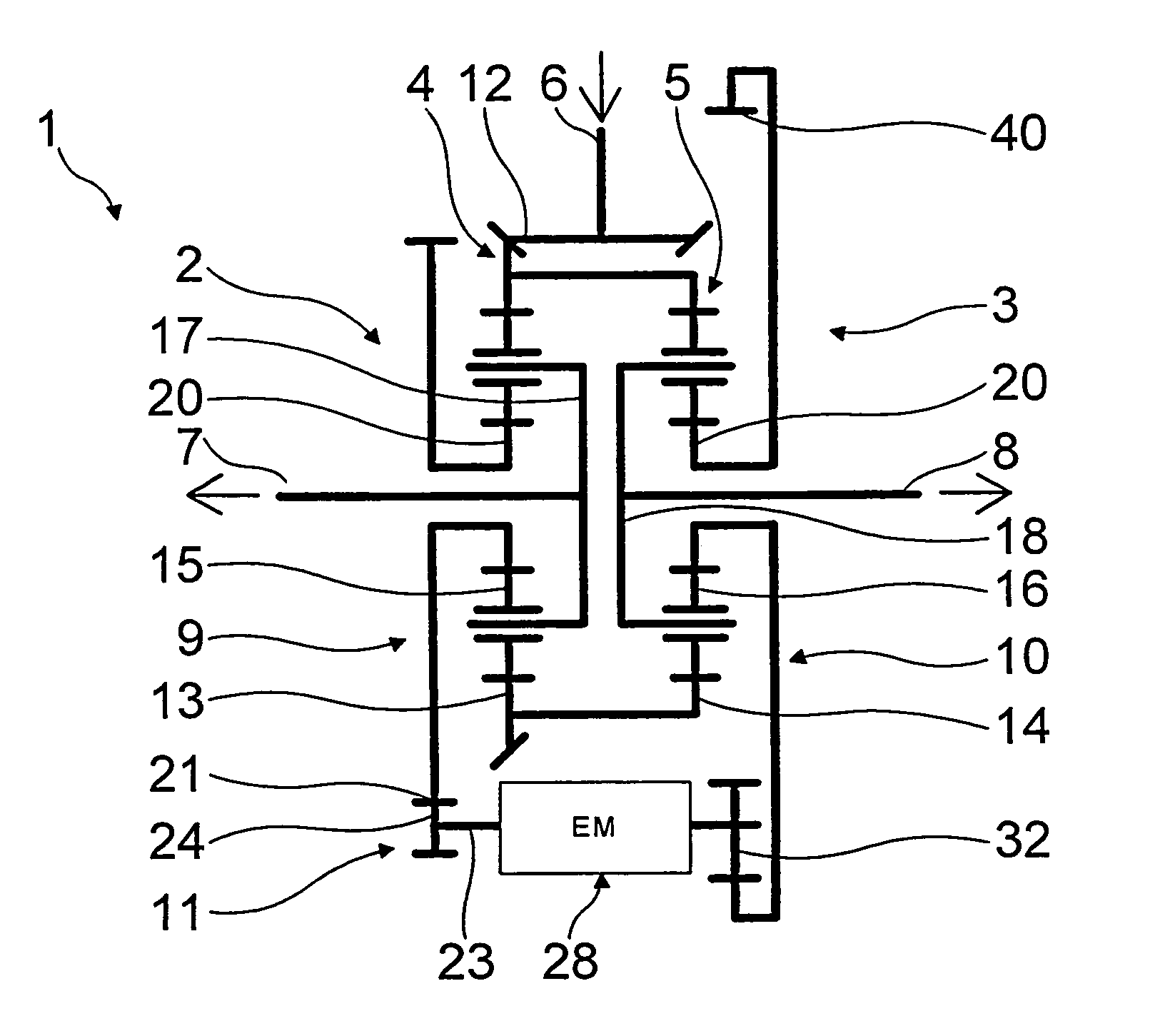
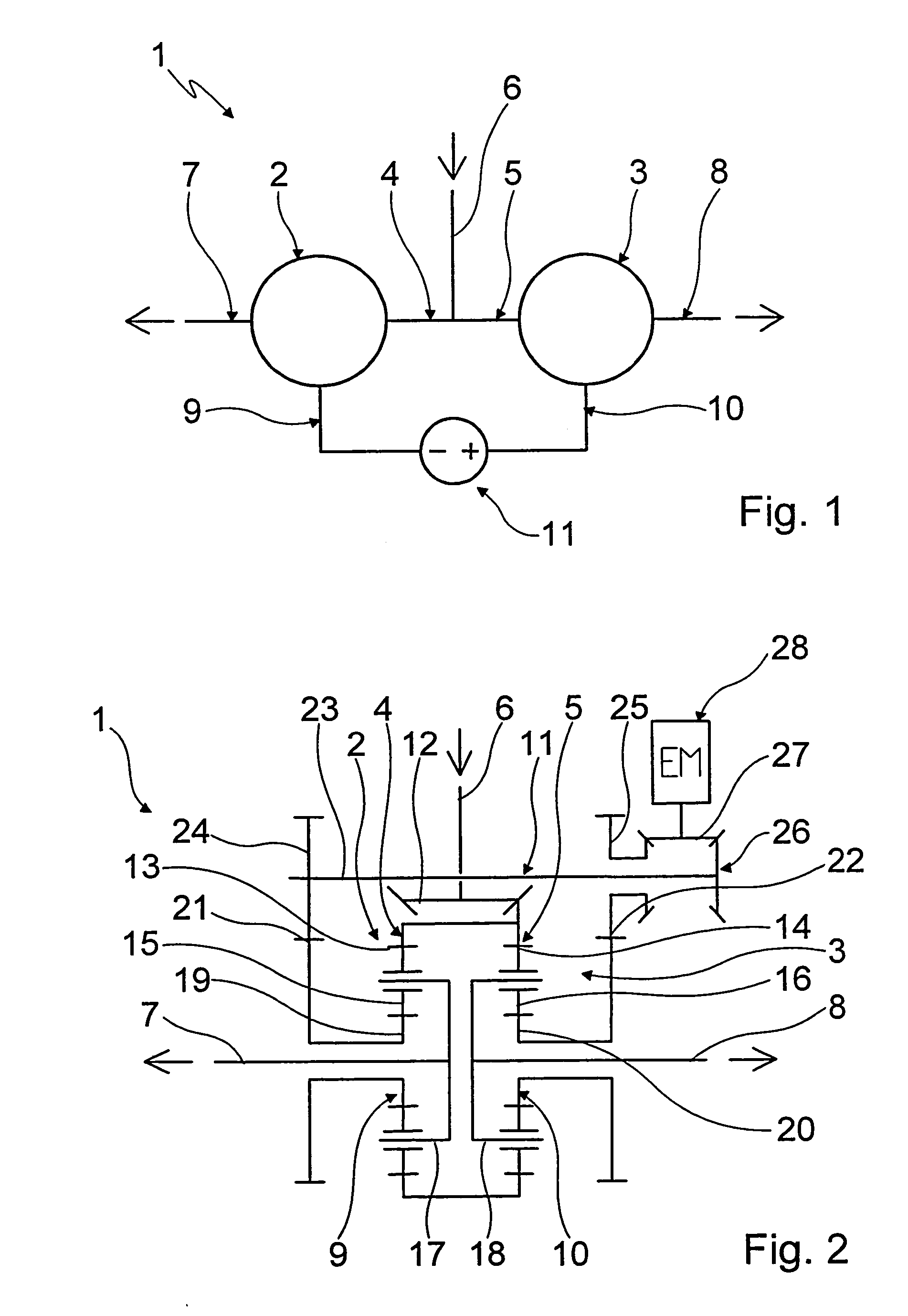
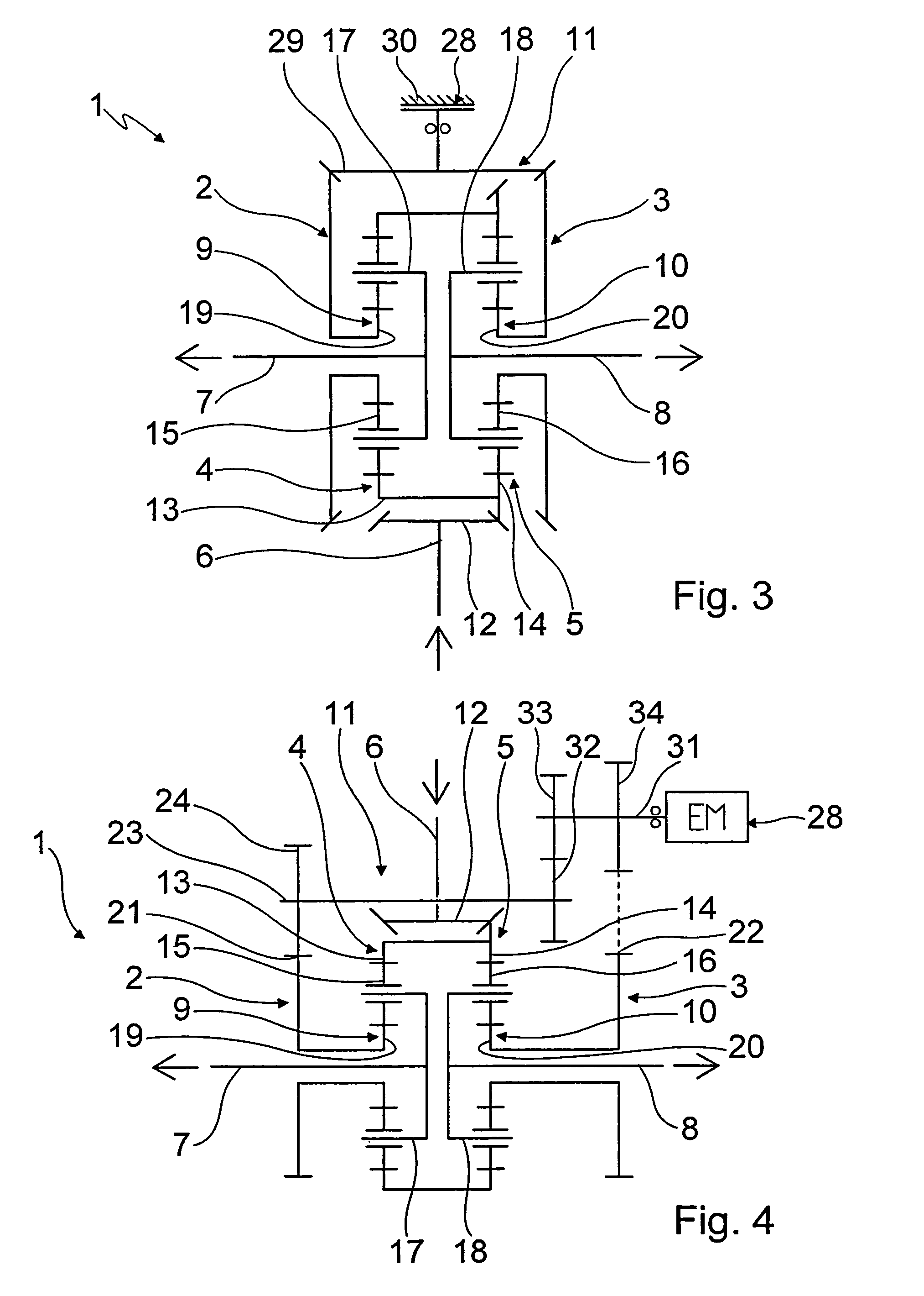
[0034]Referring to FIG. 1, it shows a basic diagram of a transmission 1 shows which can preferably be used in a vehicle as differential transmission for longitudinal distribution of a drive torque of a prime mover or for transverse distribution of a drive torque of a prime mover. With the transmission 1, it is easily possible to distribute the drive torque in a longitudinal direction as needed, that is, seen in travel direction of a vehicle, to two driven axles of a vehicle. In addition, the drive torque can be transversely distributed via the transmission 1 to the drive wheels of a driving vehicle axle of a vehicle.

[0035]The transmission 1 is designed with two planetary gear sets 2, 3 which, depending on the momentary application, can be designed as negative, positive, bevel gear or stepped planetary gear set. Each shaft 4, 5 of the two planetary gear sets 2, 3 is connected with an input shaft 6. Other shafts 7 and 8 of the planetary gear sets 2, 3 constitute each one output shaft ...


PUM


Abstract

A transmission (1) for distributing a drive torque to at least two output shafts (7, 8) which has at least two planetary gear sets (2, 3) with at least three shafts wherein each shaft (4, 5) of a planetary gear set (2, 3) is connected with one input shaft (6). Besides, each shaft of a planetary gear set (2, 3) constitutes one of the output shafts (7, 8) and at least one other shaft (9 or 10) of a planetary gear set (2 or 3) is operatively connected with one shaft (10 or 9) of one other planetary gear set (3 or 2). A torque of a shaft (9 or 10) dependent on operating state can be supported according to an operating state of the respective other shaft (10 or 9) via an operative connection (11) therewith in a manner such that when a rotational speed difference occurs between the output shafts (7, 8) a torque that changes the rotational speed difference abuts via the operative connection (11) on the planetary gear sets (2, 3).

Description

[0001]This application claims priority from German Application Serial No. 103 19 684.6 fiIed May 2, 2003.FIELD OF THE INVENTION[0002]The invention concerns a transmission for distributing a drive torque to at least two output shafts having at least two planetary gear sets with at least three shafts.BACKGROUND OF THE INVENTION[0003]In vehicles, it is known in the practice to transmit as needed to the drive wheels via a transmission a drive torque produced by a prime mover. If vehicles such as four-wheel passenger cars or four-wheel driven trucks are designed with several driven axles, the power of the prime mover in the power train of such vehicles has to be distributed to the individual drive axles.[0004]For power distribution so-called differential transmissions are used wherein the longitudinal differentials seen in driving direction are used for longitudinal distribution of the input of the prime mover to several driven axles of a vehicle. So-called transverse differentials or di...

Claims


Application Information

Patent Timeline
IPC IPC(8): F16H48/02B60K17/16F16H1/14F16H1/22F16H48/24F16H48/30
CPCB60K17/16F16H48/10F16H48/11F16H48/30F16H48/36F16H48/22F16H2048/364
Inventor GUMPOLTSBERGER, GERHARDBAASCH, DETLEF
Owner ZF FRIEDRICHSHAFEN AG
Learn More