Sensor element

a technology of sensor elements and elements, applied in the direction of magnetic measurements, liquid/fluent solid measurements, engine lubrication, etc., can solve the problems of insufficient protection of cast resin, difficult and expensive manufacture of complex geometries, and insufficient constructive efforts for protecting the sensor element. , to achieve the effect of simple configuration, high accuracy and measuremen

Active Publication Date: 2005-07-07
TI AUTOMOTIVE NEUSS
View PDF3 Cites 35 Cited by
  • Summary
  • Abstract
  • Description
  • Claims
  • Application Information

AI Technical Summary

Benefits of technology

[0018] Due to the fact that the sensor element is arranged between the rotary axis and the magnet and not the magnet between the rotary axis and the sensor element, the movable magnet is located farther away from the rotary axis such that the magnet travels a larger distance when the position of the float is changed. Due to the longer path travelled by the magnet, the magnetic field measured by the sensor element changes to a larger extent at a comparable change in the position of the float. The sensor element can thus be of smaller and compacter configuration and can measure the fill level with a higher accuracy. Further, it is sufficient to protect only the detector element of the sensor element against fuels and fuel vapors or the like since the other components do not comprise any sensitive electric elements. The contactlessly operating level indicator can thus be of simple configuration.
[0019] The magnet is preferably configured at least as a segment of a ring magnet. This results in a relatively uniform and undisturbed magnetic field which is measured by the sensor element. For further disturbance elimination the sensor element may be provided with disturbance-elimination modules, whereby the measuring accuracy is improved.
[0020] In a preferred embodiment the level indicator comprises an intermediate piece with which the lever is rotatably connected. Further, the intermediate piece comprises an opening for receiving the sensor element. The sensor element is arranged in the opening such that the detector element of the sensor element is associated with the side of the intermediate piece facing the lever. The sensor element can thus, for example, be guided outside the fuel tank through the opening of the intermediate piece and, in particular partly, into the fuel tank. In particular the sensor element comprises a projection which, in the form of a stopper, bears on the side of the intermediate piece facing away from the lever. This in particular allows the detector element to be arranged in a completely encapsulated condition at the side of the intermediate piece facing the lever, wherein the connection with the lid and the conductor ends of the conductors are disposed at the side of the intermediate piece facing away from the lever. Owing to this arrangement the detector element of the sensor element is further protected by the intermediate piece, for example due to the fact that the intermediate piece acts as a splash guard.
[0021] The invention further relates to a level indicator assembly comprising a fuel tank and a level indicator connected therewith, which is in particular configured as described above. The fuel tank comprises a receiving opening for receiving a sensor element or an intermediate piece. The sensor element disposed in the receiving opening such that the detector element is arranged inside the fuel tank and the conductor ends of the electric conductors are arranged outside the fuel tank. If existing, in particular the connection between a cover element and a lid of the sensor element is also disposed outside the fuel tank. With this arrangement a reliable protection of the detector element against the fuel in the fuel tank can be realized with the aid of simple constructive means. The improved protection of the detector element against fuel and / or fuel vapors increases the service life of the level indicator assembly.

Problems solved by technology

A drawback of such a sensor element is that considerable constructive efforts are required for protection of the sensor element.
It is necessary to use components with complicated geometries which are difficult and expensive to manufacture.
Further, the cast resin does not offer sufficient protection since fuel, which flows along the housing wall thus coming in contact with the cast resin, gradually diffuses through the cast resin such that the sensor element becomes, for example, damaged by corrosion, which results in a relatively short service life of the sensor element.

Method used


Image

  • Sensor element
  • Sensor element
  • Sensor element

Examples


first embodiment

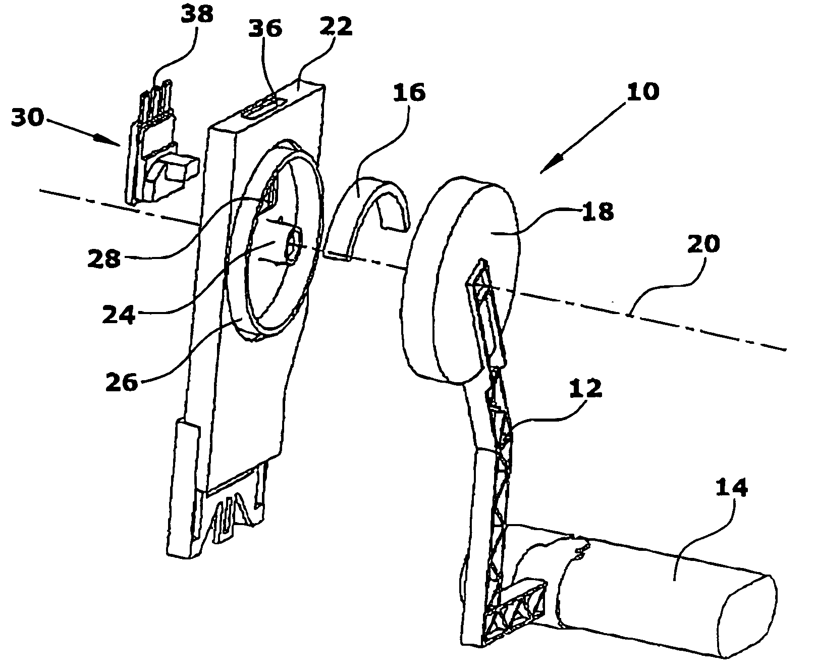
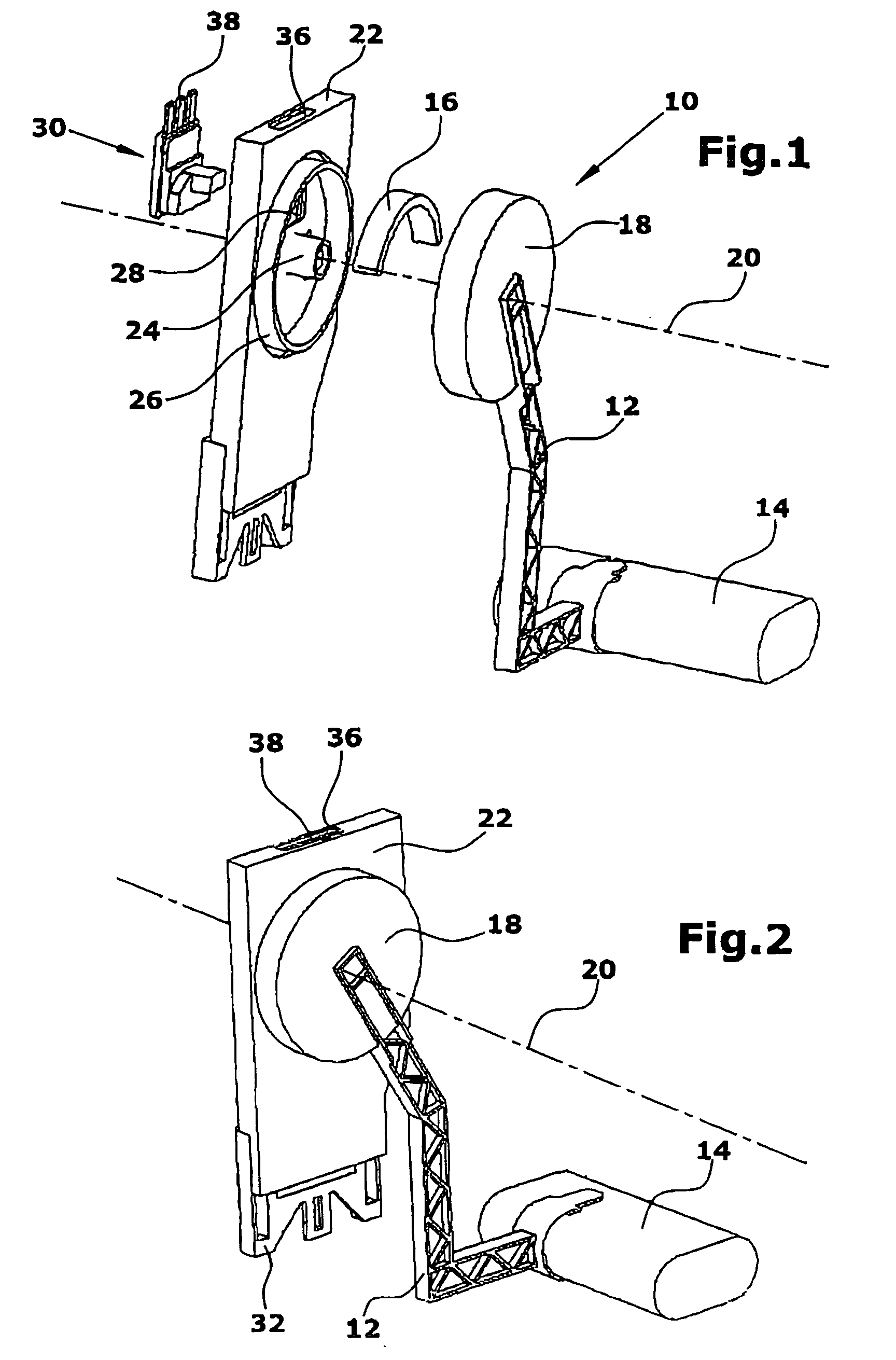
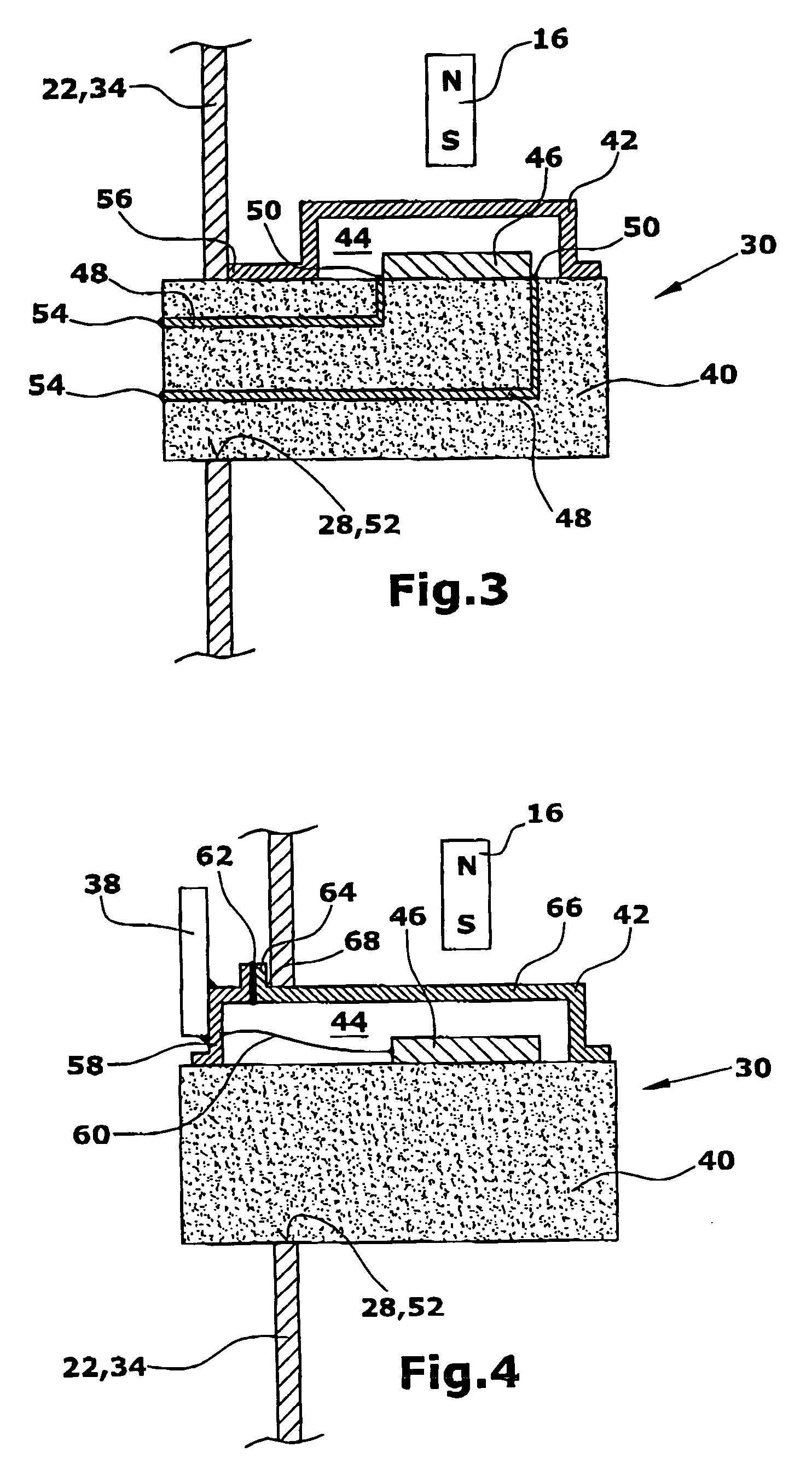
[0032] In the sensor element 30 (FIG. 3) a metal cover element 42 is soldered to a base element 40. Inside an encapsulated space 44 formed by the base element 40 and the cover element 42 a detector element 46 is arranged. The detector element 46 may be a Hall effect element and / or an AMR sensor and / or a GMR sensor. The detector element 46 is placed onto the ceramic base element 40. The base element 40 comprises conductor conduits 48 which are connected via solder joints 50 with the detector element 46.

[0033] The sensor element 30 is arranged in an opening which may be the opening 28 of the intermediate piece 22 or a receiving opening 52 of the fuel tank 34.

[0034] The sensor element 30 is disposed in the opening 28 and / or the receiving opening 52 such that the detector element 46 is arranged inside the fuel tank 34. Thereby the conductor ends 54 of the conductor conduits 48 are arranged outside the fuel tank 34, whereby the conductor ends 54 can be soldered, outside the fuel tank 34...

second embodiment

[0035] In the Hall effect sensor element 30 (FIG. 4) the cover element 42 comprises contact elements 58 which are connected via electric conductors 60 with the detector element 46. Each contact element 58 is connected, for example by soldering, with an electric terminal 38. The contact elements 58 are insulated towards the remaining cover element 42 with the aid of an insulating means 62 such that short-circuits are prevented.

[0036] The cover element 42 comprises a projection 64 which is arranged at a right angle to a surface 66 of the cover element 42. Thus a right angle 68 is formed between the projection 64 and the surface 66. During assembly the sensor element 30 is inserted, in FIG. 4, from the left into the opening 28,52 such that the projection 64, acting as a stopper, limits the insertion depth. Due to the right angle 68 both the projection 64 and the surface 66 are, in the built-in condition, in contact with the intermediate piece 22 and / or the fuel tank 34.

third embodiment

[0037] In the sensor element 30 (FIG. 5) the sensor element 30 is provided with a cover capsule comprising the cover element 42 and a lid 70. The base element 40 is completely arranged inside the cover capsule. The cover element 42 comprises a nose 72 which is arranged at a distance to the bottom 74 of the cover element 42, which corresponds to the thickness of the base element 40. This allows the base element 40 to be connected, in a fixed positional arrangement, with the cover element such that soldering is not necessary. Accordingly, the lid 70 comprises a recess 76 which also corresponds to the thickness of the base element 40. The base element 40 is held by both the cover element 42 and the lid 70.

[0038] The lid 70 and the cover element 42 are preferably integrally connected with each other, in particular by soldering. To connect the detector element 46 with an evaluation unit and / or a voltage source, the lid 70 further comprises a connecting opening 78 through which the conduc...


PUM


Abstract

A sensor element (30) measures a Hall voltage generated by a movable magnet (16). For this purpose, the sensor element (30) comprises a ceramic base element (40) which has connected therewith a detector element (46). The detector element (46) is protected with the aid of a cover element (42) against an aggressive environment produced by fuel or fuel vapors in a fuel tank (34) of a motor vehicle. The detector element (46) has connected therewith electric conductors (60) which are routed through the cover element (42) and/or the base element (40) for connecting the detector element (46) with a voltage source and/or an evaluation unit. The cover element (42) and possibly the base element (40) reliably encapsulate the detector element (46) against the aggressive environment such that by simple constructive measures the service life of the sensor element (30) is increased.

Description

BACKGROUND OF THE INVENTION [0001] 1. Field of the Invention [0002] The present invention relates to a sensor element for contactlessly measuring a magnetic field in an aggressive environment, in particular for use in a fuel tank of a motor vehicle. [0003] 2. Description of the Related Art [0004] From DE 101 42 618 A1 a contactlessly operating level indicator is known which uses a Hall effect sensor as a sensor element for measuring a fill level in a fuel tank, said Hall effect sensor detecting the magnetic field of a magnet. The magnet is connected via a lever with a float such that the measured magnetic field of the magnet varies as a function of the fill level in the fuel tank. The lever is rotatably supported via a rotary axis. The rotary axis is partially embraced by the magnet configured as a ring magnet. The ring magnet is arranged between the Hall effect sensor and the rotary axis. The magnet is disposed in a two-piece housing, wherein the housing halves are closed in a liqu...

Claims


Application Information

Patent Timeline
Patent Type & Authority Applications(United States)
IPC IPC(8): G01F23/38G01R33/07G01R33/09
CPCG01R33/07G01F23/38
Inventor KLEINEN, ALFREDSCHREUDER, PETERHENSCHEL, MATTHIASLAHN, BERND JUERGEN
Owner TI AUTOMOTIVE NEUSS
Why Eureka
Try Eureka