Forging apparatus

a technology of forging apparatus and forging force, which is applied in forging/pressing/hammering apparatus, forging/hammering/pressing machines, forging presses, etc., can solve the disadvantage of difficult lubricating conditions, limited forging force magnitude, and high construction complexity, and achieves simple construction means. , the effect of high impact ra

Inactive Publication Date: 2013-02-14
GFM GMBH
View PDF3 Cites 2 Cited by
  • Summary
  • Abstract
  • Description
  • Claims
  • Application Information

AI Technical Summary

Benefits of technology

[0005]The invention is therefore based on the object of providing a forging apparatus of the kind mentioned above in such a way that large forging forces can be provided in combination with high impact rates, which is achieved with comparatively simple constructional means.

Problems solved by technology

The advantage of these eccentric shaft drives, which is the realization of large forging forces in combination with high impact rates, is offset by the disadvantage of a high constructional complexity.
If synchronized hydraulic drives are used as lifting drives, a simpler construction is obtained but the achievable impact rates remain limited.
The difficult lubricating conditions and the forging forces which are limited in their magnitude are disadvantageous.
It is especially disadvantageous in these known constructions that the forging forces are removed via the connecting rods to the live ring, which therefore needs to be arranged in an especially deflection-resistant way when low forging tolerances need to be observed.
A deflection-resistant live ring belongs to the moved masses however, which has a disadvantageous effect on the drive and the lifting frequency of the tool holder.
Moreover, an externally disposed live ring has a negative effect on a compact configuration of such forging apparatuses.

Method used


Image

  • Forging apparatus
  • Forging apparatus
  • Forging apparatus

Examples


Embodiment Construction

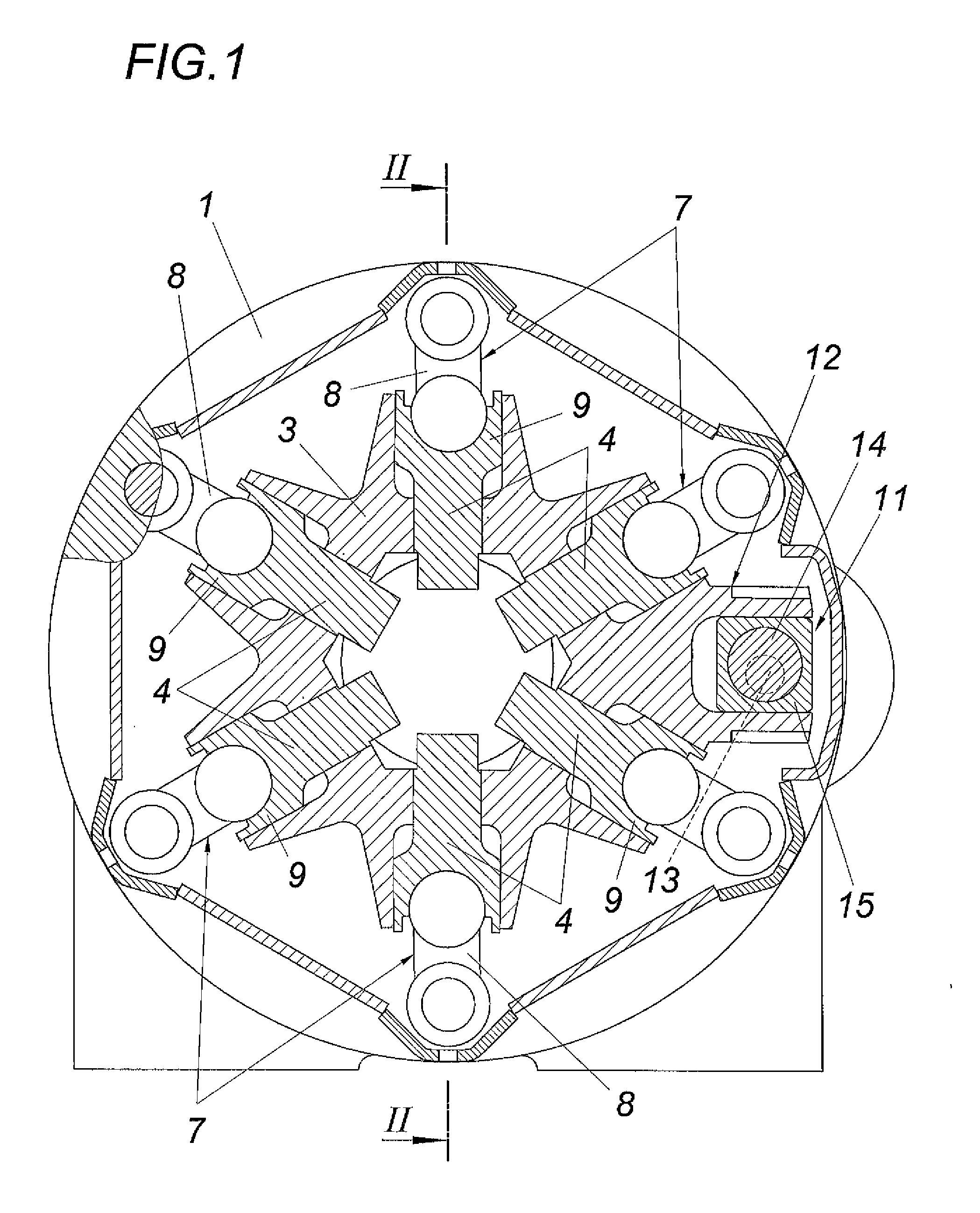
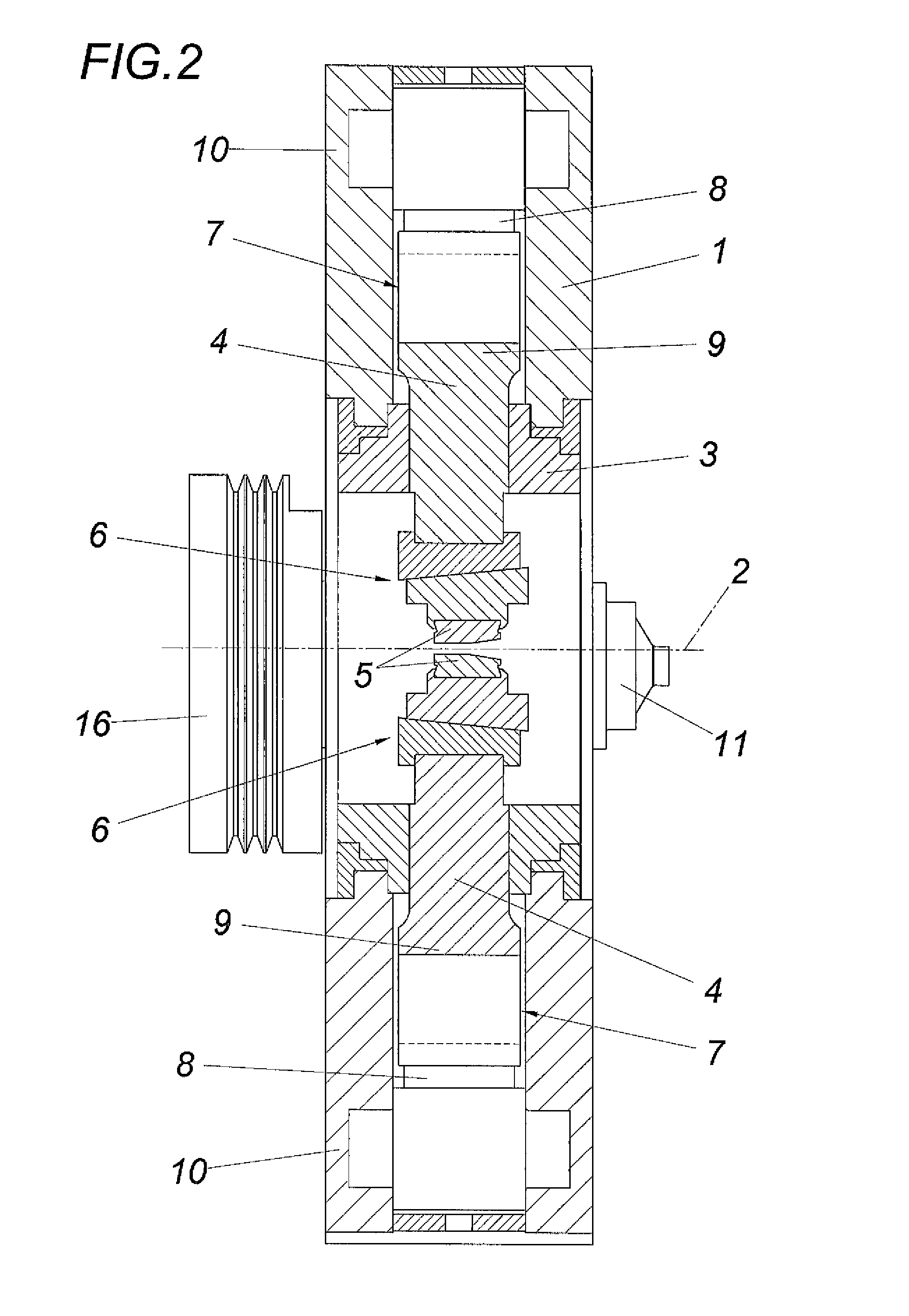
[0016]As is shown in FIGS. 1 and 2, the forging apparatus comprises a housing 1 and a frame 3 which is rotatably mounted about a forging axis 2 in the housing 1 and which accommodates tool holders 4 which are radially guided with respect to the forging axis 2. Said tool holders 4 are equipped with forging tools 5 according to FIG. 2, which are connected via wedge gears 6 for setting the lifting position of the forging tools 5 on the tool holders 4. Lifting drives 7 are associated with the tool holders 4 for activating the forging tools 5, which lifting drives respectively comprise a connecting rod 8 which pivotably rests via abutments 9, 10 on the associated tool holder 4 on the one hand and on the housing 1 on the other hand. If the frame 3 is rotated with respect to the fixed housing 1, the abutments 9 are also rotated in relation to the abutments 10 of the connecting rods 8 with respect to the forging axis 2 with the consequence that the tool holders 4 in the frame 3 are radially...


PUM

PropertyMeasurementUnit
forging forcesaaaaaaaaaa
radial forging forcesaaaaaaaaaa
radial displacementaaaaaaaaaa

Abstract

A forging apparatus is described, comprising forging tools (5) which are arranged in a centrically symmetrical way about a forging axis (2) and whose tool holders (4) radially guided in a frame (3) are connected with lifting drives (7), which each comprise one respective connecting rod (8) that is pivotably supported via abutments (9) on a housing (1) on the one hand and on the tool holder (4) on the other hand, and comprising a common drive for the lifting drives (7) which comprises a torsional vibration drive (11) for at least one actuator (12) for the one of the two abutments (9, 10) of the connecting rods (8), which actuator is rotatably held about the forging axis (2). In order to ensure advantageous constructional conditions, it is proposed that the frame (3) forms the actuator (12) of the common drive for the lifting drives (7), and that the torsional vibration drive (11) is provided between the housing (1) and the frame (3) which is rotatably held about the forging axis (2).

Description

1. FIELD OF THE INVENTION[0001]The invention relates to a forging apparatus, comprising forging tools which are arranged in a centrically symmetrical way about a forging axis and whose tool holders radially guided in a frame are connected with lifting drives, which each comprise one respective connecting rod that is pivotably supported via an abutments on a housing on the one hand and on the tool holder on the other hand, and comprising a common drive for the lifting drives which comprises a torsional vibration drive for at least one actuator for the one of the two abutments of the connecting rods, which actuator is rotatably mounted about the forging axis.[0002]2. DESCRIPTION OF THE PRIOR ART[0003]Forging apparatuses with forging tools which are arranged in a rotationally symmetrical way about a forging axis and which are usually diametrically opposite of one another with respect to the forging axis comprise different lifting drives for the forging tools. It is therefore known for ...

Claims


Application Information

Patent Timeline
Patent Type & Authority Applications(United States)
IPC IPC(8): B21J7/16
CPCB21J7/16
Inventor SEEBER, ALFRED
Owner GFM GMBH
Why Eureka
Try Eureka