
Metal fiber surface combustion structure thermal test method and device

A metal fiber, surface combustion technology, applied in the field of thermal testing, can solve the problem of high impact rate nonlinear time-varying heat flow simulation ability, difficult and large gradient heat flow distribution, and difficult component full size. Simulation, etc.

Active Publication Date: 2021-02-26
CHINA ACADEMY OF SPACE TECHNOLOGY
View PDF7 Cites 0 Cited by
  • Summary
  • Abstract
  • Description
  • Claims
  • Application Information

AI Technical Summary

Problems solved by technology

However, in response to the new requirements of the aerothermal simulation of the above-mentioned complex structures, the traditional thermal test method has many deficiencies
For example, the current test system is difficult to simulate the large gradient heat flow distribution on the surface and the high impact rate nonlinear time-varying heat flow simulation ability
From the perspective of traditional test methods, high-temperature wind tunnels mostly use step-type thermal power up and down methods to realize unsteady thermal environment simulations, so it is difficult to accurately simulate rapidly changing complex nonlinear thermal environment history; while radiation heating equipment such as quartz lamps, although Excellent electrical control performance, which can realize nonlinear time-varying heat flow simulation with high impact rate, but it is difficult to accurately simulate the large gradient heat flow distribution on the surface of the structure
Moreover, limited by the installation form of the test system, it is difficult for the current system to adapt to the heat flow loading on the surface of large-scale complex structures.
The size of traditional high-temperature wind tunnel specimens is limited, and it is difficult to realize full-scale simulation of components; while radiation heating equipment such as quartz lamps are installed in partitions, it is difficult to adapt to complex aerodynamic shapes

Method used


Image

  • Metal fiber surface combustion structure thermal test method and device
  • Metal fiber surface combustion structure thermal test method and device
  • Metal fiber surface combustion structure thermal test method and device

Examples


Embodiment Construction

[0033] In order to more clearly describe the embodiments of the present invention or the technical solutions in the prior art, the following will briefly introduce the drawings that are used in the embodiments. Apparently, the drawings in the following description are only some embodiments of the present invention, and those skilled in the art can also obtain other drawings according to these drawings without creative efforts.

[0034] When describing the embodiments of the present invention, the terms "vertical", "transverse", "upper", "lower", "front", "rear", "left", "right", "vertical", " The orientation or positional relationship expressed by "horizontal", "top", "bottom", "inner" and "outer" is based on the orientation or positional relationship shown in the relevant drawings, which are only for the convenience of describing the present invention and simplifying the description, and It is not to indicate or imply that the device or element referred to must have a particu...


PUM


Abstract

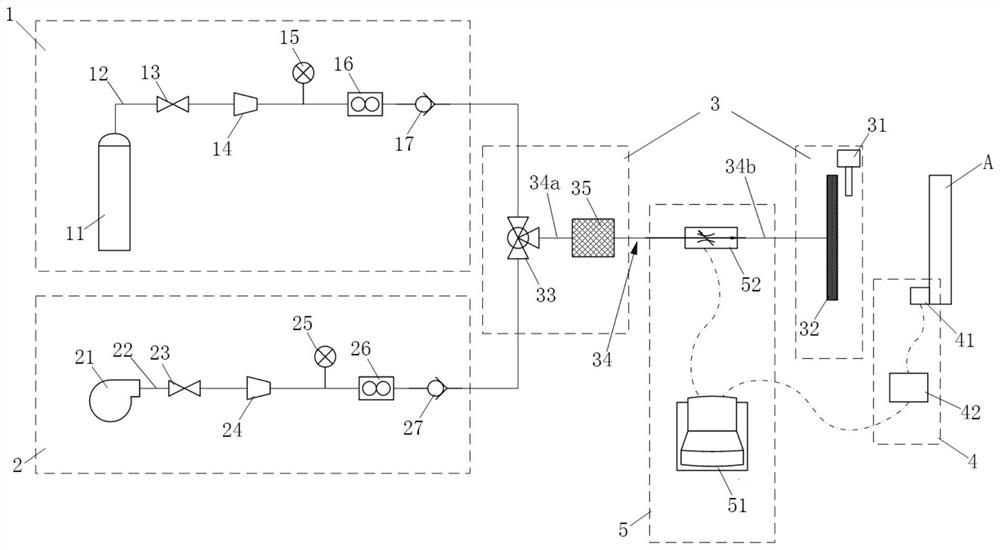
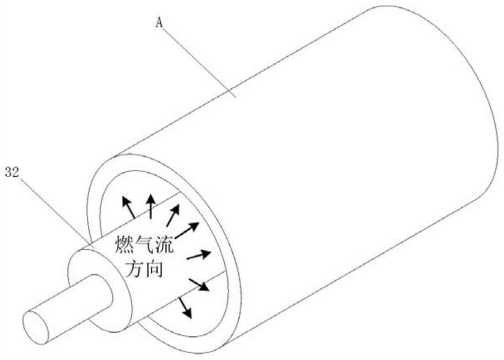
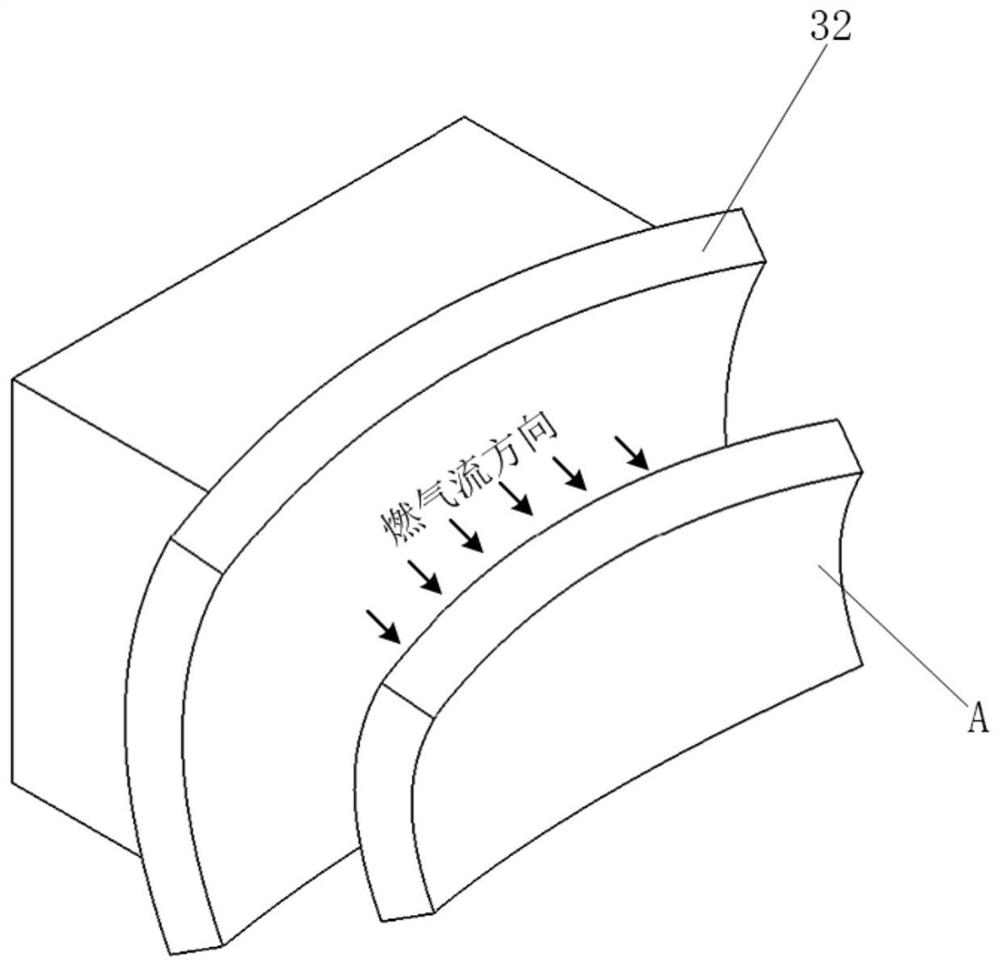
The invention relates to a metal fiber surface combustion structure thermal test method and device, and the method comprises the following steps: a, mixing fuel gas with a gas combustion improver to form a mixed gas, and enabling the mixed gas to be conveyed along at least one gas path; b, igniting mixed gas at the tail end of the gas path, enabling combustion flame to penetrate through an attachment body, wherein all points of at least one surface of the attachment body correspond to all points of the heated surface of the test piece, and therefore fuel gas formed through combustion is sprayed to the heated surface of the test piece to heat the heated surface; and c, measuring thermal load parameters of the heated surface of the test piece corresponding to each gas path in real time, andcontrolling the flow of the mixed gas in the corresponding gas path in real time according to the thermal load parameters. According to the invention, the attachment formed by weaving the metal fibersis used as an attachment of the mixed gas combustion flame, so that the combustion surface can adapt to the complex shape of the test piece, and full-size simulation is realized.

Description

technical field [0001] The invention relates to the technical field of thermal testing, in particular to a structural thermal testing method and device based on metal fiber surface combustion. Background technique [0002] With the development of aerospace technology, hypersonic vehicles have become an important development direction of major aerospace countries. This type of aircraft will be subjected to thermal loads brought by hypersonic airflow during flight. In order to ensure the safety of the aircraft and keep the interior of the aircraft within the allowable temperature and pressure range, a thermal protection structure must be used. The leading edge, wing rudder structure, air inlet, nozzle and other key parts of this type of aircraft adopt complex surface design, and the surface thermal load distribution gradient is large during hypersonic flight, and the size is often large. Maneuvering or super-maneuvering orbit changes are often required, and the thermal load h...

Claims


Application Information

Patent Timeline
Patent Type & Authority Applications(China)
IPC IPC(8): B64G7/00
CPCB64G7/00
Inventor 齐玢阿嵘董素君王日侯砚泽
Owner CHINA ACADEMY OF SPACE TECHNOLOGY
Learn More