Magnetic resonance imaging system

a magnetic resonance imaging and magnetic field technology, applied in the field of magnetic resonance imaging systems, can solve the problems of difficult to meet the contradictory requirements i, and the inability to meet the magnetic so as to enhance the feeling of being not confined and reduce the magnetomotive force of the superconductive coil

Inactive Publication Date: 2006-06-06
MITSUBISHI ELECTRIC CORP
View PDF28 Cites 18 Cited by
  • Summary
  • Abstract
  • Description
  • Claims
  • Application Information

AI Technical Summary

Benefits of technology

[0011]The present invention has been implemented in order to solve the foregoing problem, and provides a magnetic resonance imaging system in which the two contradictory requirements, i.e., enhancing the feeling of being not confined, by enlarging the subject-insertion space, and decreasing magnetomotive force of the superconductive coils by bringing the superconductive coils as close as possible to a subject, can be met in a good balance.
[0013]According to the present invention, a magnetic resonance imaging system can be provided in which the two contradictory requirements, i.e., enhancing the feeling of being not confined by enlarging the subject-insertion space and decreasing magnetomotive force of the superconductive coils by bringing the superconductive coils as close as possible to a subject, can be met in a good balance.

Problems solved by technology

However, in the first conventional magnetic resonance imaging system, because the gradient-magnetic-field and radio-frequency coils, which are unillustrated, are provided between the top and bottom vacuum containers, the installation spaces of the gradient-magnetic-field and radio-frequency coils prevent the superconductive coils from being brought close to the subject.
As discussed above, there has been a problem in that two contradictory requirements i.e., providing the subject with the feeling of not being confined and decreasing the magnetomotive force of the superconductive coils, are difficult to meet.

Method used


Image

  • Magnetic resonance imaging system
  • Magnetic resonance imaging system
  • Magnetic resonance imaging system

Examples


embodiment 1

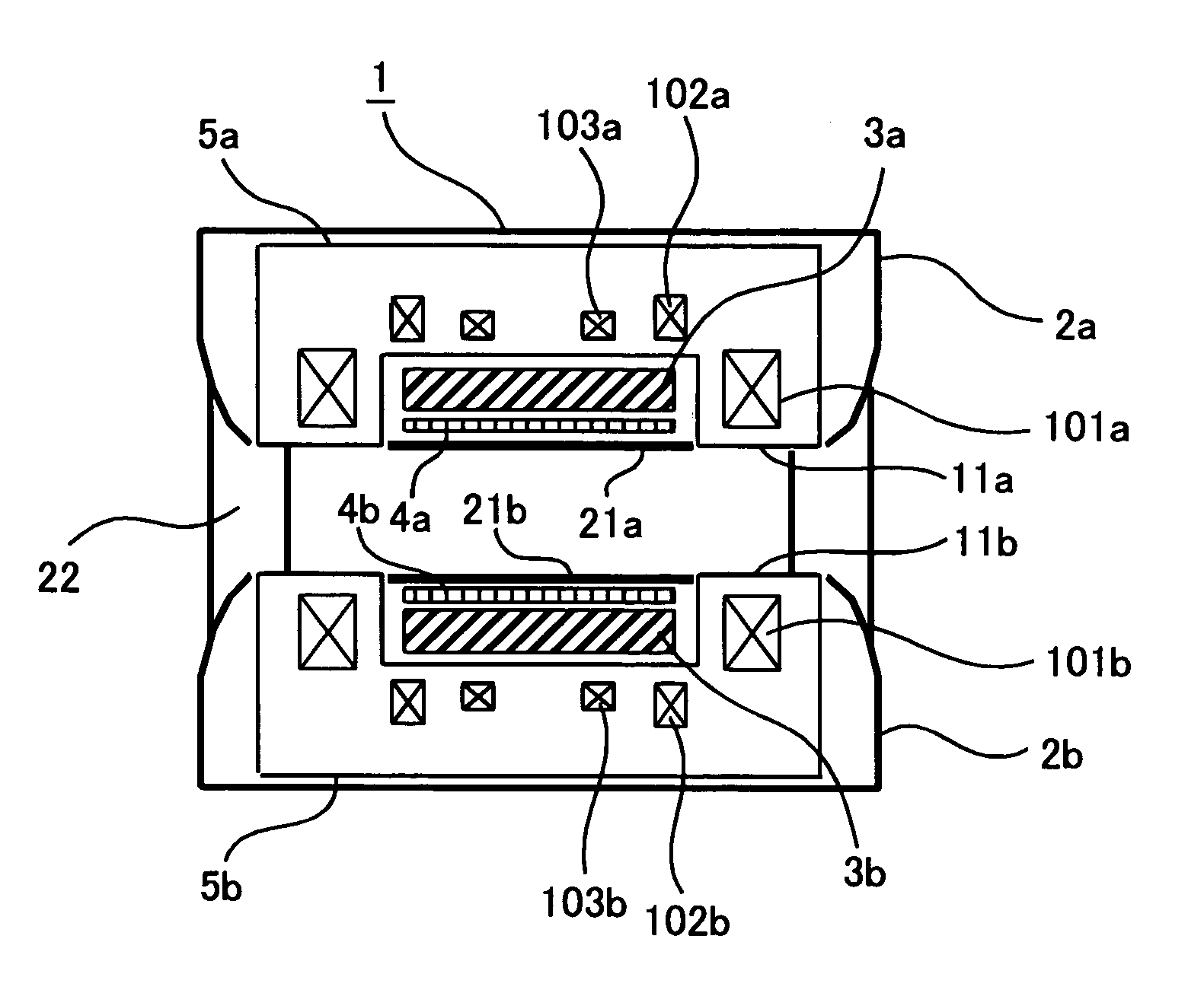
[0020]FIG. 1 is a side view for explaining Embodiment 1 of magnetic resonance imaging systems to which the present invention is applied.

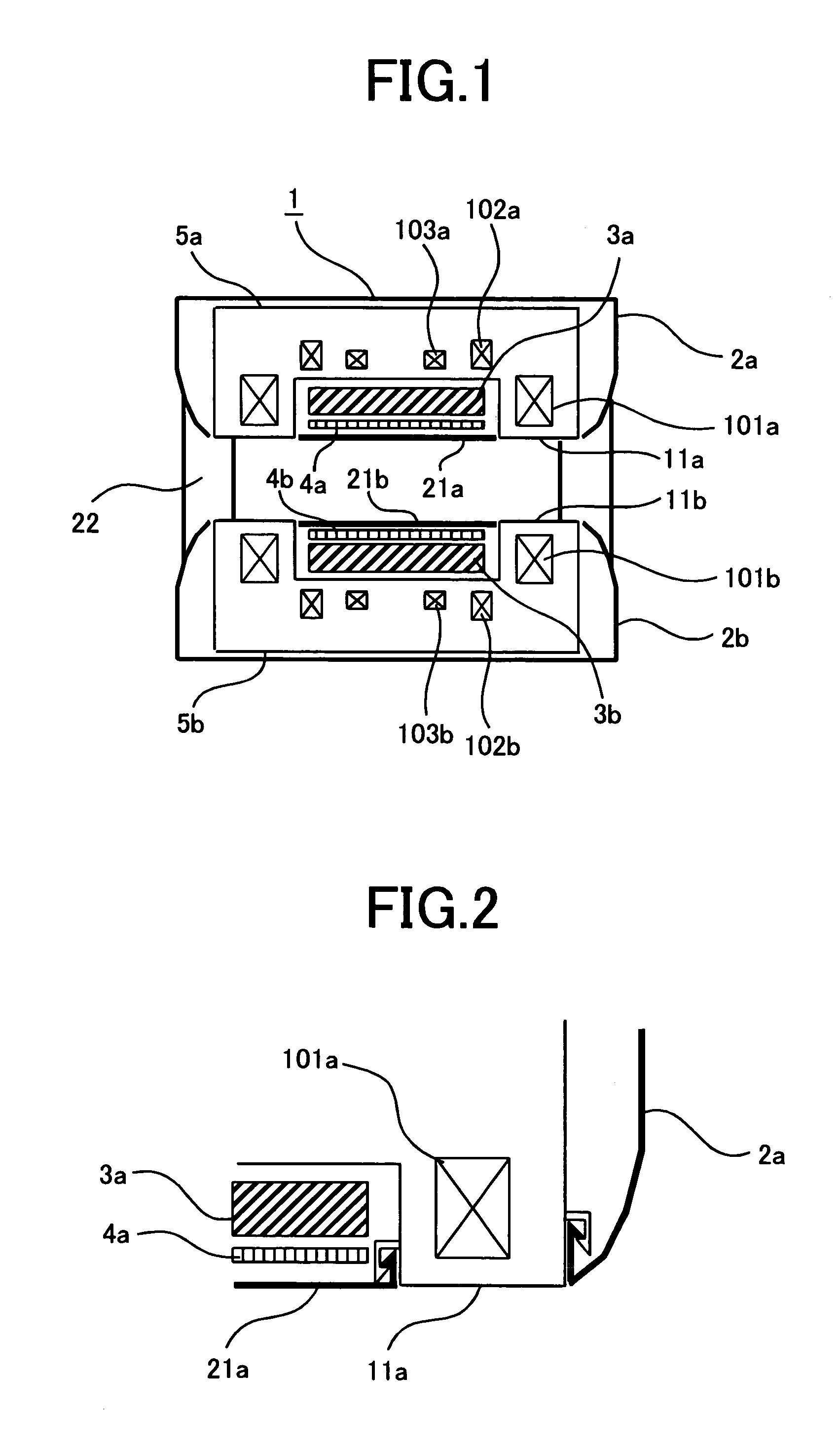
[0021]FIG. 2 is an enlarged view of principal parts in FIG. 1. The magnetic resonance imaging system according to Embodiment 1 is open-type.

[0022]A superconductive electromagnetic device 1 generating a static magnetic field to be applied to a subject is provided with superconductive coils 101a, 102a and 103a illustrated at the top side of FIG. 1, and with superconductive coils 101b, 102b and 103b illustrated at the bottom side of FIG. 1. The superconductive coils 101a through 103a are contained within a vacuum container 5a at the top side via a cooling container filled with liquid helium. Similarly, the superconductive coils 101b through 103b are contained within a vacuum container 5b at the bottom side via a cooling container filled with liquid helium. The vacuum containers 5a and 5b are facing each other, flanking the subject-insertion space with ...

embodiment 2

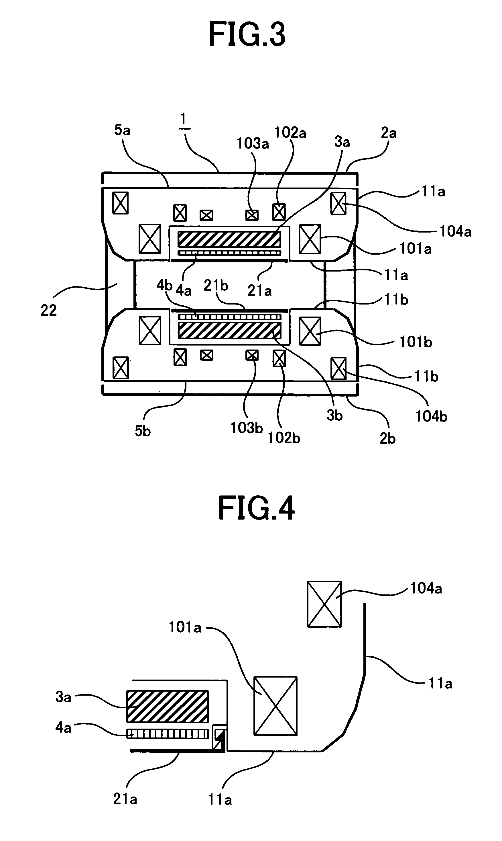
[0038]FIG. 3 is a side view of a magnetic resonance imaging system, for explaining Embodiment 2. FIG. 4 is an enlarged view of principal parts in FIG. 3. Embodiment 2 is an another aspect of Embodiment 1, wherein circumferential-surface portions of the vacuum containers 5a and 5b are also coated with the thin resin sheets 11a and 11b. In this way, in cases where a magnetic resonance imaging system is produced with the same circumferential dimensions as ever before, the circumferential dimensions of the vacuum containers 5a and 5b can be increased. In consequence, the external diameters of the superconductive coils 101a and 101b can be enlarged.

[0039]In this case, as well, an effect of decreasing the magnetomotive force of the superconductive coils is demonstrated, and a result has been obtained that the magnetomotive force is in reverse proportion to the external diameter, of the superconductive coil, raised approximately to the third power. For example, when the external diameters ...

embodiment 4

[0045]FIG. 6 is a side view of a magnetic resonance imaging system, for explaining Embodiment 4. Embodiment 4 is another aspect of Embodiment 3, wherein the ends of the cylinder or the vacuum containers 5c, in Embodiment 3, are also coated with the thin resin sheets 11c. In this way, in cases where a magnetic resonance imaging system is produced with the same axial length as ever before, the axial length of the vacuum containers 5c can be increased. In consequence, the superconductive coils 101c and 101d can be positioned closer to both ends of the cylinder. Meanwhile, high uniformity in the order of ppm is required of a static magnetic field for a magnetic resonance imaging system, and error components are generally cancelled out each other by combining a plurality of superconductive coils. Therefore, when the winding diameters of the superconductive coils 101c through 103c, and 101d through 103d are unchanged, the larger the axial length of the vacuum container 5c is, the more enh...


PUM


Abstract

A magnetic resonance imaging system is provided in which the two contradictory requirements, i.e., enhancing the feeling of being not confined by enlarging the subject-insertion space and decreasing magnetomotive force of the superconductive coils by bringing the superconductive coils as close as possible to a subject, can be met in a good balance.In a magnetic resonance imaging system that includes a superconductive electromagnetic device for generating a static magnetic field to be applied to a subject, a gradient-magnetic-field coil for forming a gradient magnetic field by tilting the magnetic-field strength of the static magnetic field, and a radio-frequency coil for transmitting a radio-frequency magnetic field to the subject and then receiving nuclear magnetic-resonance signals from the subject, a vacuum container for the superconductive electromagnetic device thereof has a recess; the gradient-magnetic-field coil and the radio-frequency coil thereof are accommodated in the recess; and a cosmetic cover that is fit into the recess and is supported by the wall surfaces of the recess is included therein.

Description

BACKGROUND OF THE INVENTION[0001]1. Field of the Invention[0002]The present invention belongs to a technological field related to magnetic resonance imaging systems for performing medical tomography by means of magnetic resonance phenomena, and particularly to a cosmetic cover for a superconductive electromagnetic device.[0003]2. Description of the Related Art[0004]Magnetic resonance imaging systems utilizing a superconductive electromagnetic device include tunnel-type and open-type systems when categorized according to the contours of vacuum containers for incorporating superconductive coils and the like. The vacuum container for a tunnel-type system has a cylindrical contour and a bore into which a subject is inserted. In contrast, the vacuum containers for an open-type system are in a top-and-bottom pair or in a left-and-right pair, facing each other, and a subject is inserted into the space between the facing vacuum containers.[0005]In the open-type system, the two facing vacuum...

Claims


Application Information

Patent Timeline
Patent Type & Authority Patents(United States)
IPC IPC(8): G01V3/00
CPCG01R33/3815G01R33/3806
Inventor TANABE, HAJIME
Owner MITSUBISHI ELECTRIC CORP
Why Eureka
Try Eureka