Foot control

a technology of foot control and power-driven functions, which is applied in the field of foot control, can solve the problems of increasing engineering development and manufacturing costs of the examination table supplier, doctor may accidentally depress the wrong pedal, and the control of the foot control which incorporates separate pedals for controlling the power-driven functions of the examination table is susceptible, so as to facilitate the control of the power-driven functions and facilitate interchang

Active Publication Date: 2006-06-13
MIDMARK
View PDF19 Cites 20 Cited by
  • Summary
  • Abstract
  • Description
  • Claims
  • Application Information

AI Technical Summary

Benefits of technology

[0012]In accordance with another aspect of the present invention, the keypad and the membrane switch define a pair of independent operating stations on the foot control which are responsive to selective pressure applied on the keypad by a user's foot. Each of the operating stations is configured to control two independent power-driven functions of the medical apparatus. In one embodiment, each of the first and second operating stations is configured to control two reversible power-driven functions of the medical apparatus. The pair of operating stations are particularly oriented so that a user is able to easily actuate the power-driven functions controlled by the pair of operating stations simply by pivoting the user's foot about its heel. This minimizes the risk that a user will lose orientation of the user's foot relative to the foot control which may otherwise occur if a user is required to lift, shift and place the user's foot on the foot control to actuate the power-driven functions of the medical apparatus. Each operating station further permits a user to simultaneously actuate two of the power-driven functions provided at each of the operating stations by selectively applying pressure to two of the actuation keys at the same time.
[0013]In accordance with another aspect of the present invention, the flexible keypad is interchangeable with one or more other keypads having a different configuration for actuating the actuation keys so that the control functionality of the foot control can be changed while the membrane switch remains unchanged. In this way, a common membrane switch can be provided for the foot control, and the keypads can be easily interchanged and mounted on top of the foot control to provide different options for controlling the power-driven functions of the medical apparatus. One keypad may be mounted on the foot control to provide control of all of the available power-driven functions of the medical apparatus while a differently configured keypad may be mounted on the foot control to provide control of less than all of the available power-driven functions of the medical apparatus. In this way, the foot control can be readily configured for controlling different capabilities of the same model of medical apparatus purchased by customers or to configure the foot control for controlling different models of the medical apparatus having different power-driven function capabilities. In either situation, the membrane switch remains unchanged and only the configuration of the keypad needs to be changed for the particular application.

Problems solved by technology

Foot controls which incorporate separate pedals for controlling the power-driven functions of the examination table are susceptible, in use, to certain problems.
During a treatment or examination procedure, the doctor may lose orientation of the doctor's foot in relation to the pedals as the doctor moves around so that the doctor may accidently depress the wrong pedal for the intended movement of the examination table.
This increases the engineering development and manufacturing costs for the examination table supplier.

Method used


Image

  • Foot control
  • Foot control
  • Foot control

Examples


Embodiment Construction

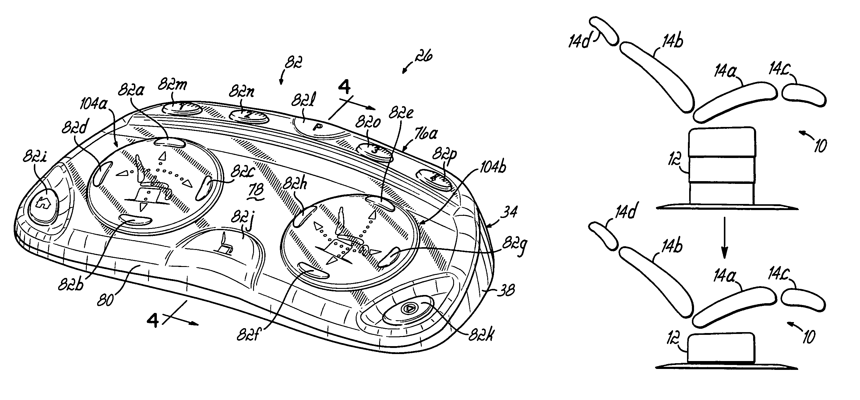
[0024]Referring to the drawings, and to FIGS. 7–12 in particular, an exemplary examination table 10 is shown which includes a power-operated telescoping base 12 for supporting the examination table 10 above a floor surface. The base 12 supports a seat section 14a, back section 14b, foot and leg support section 14c, and headrest section 14d which define an adjustable patient support surface 16 for supporting a patient in a variety of examination and treatment positions. The seat section 14a, back section 14b and foot and leg support section 14c are all hingedly connected and may be adjusted under power into multiple work positions which may be selected in accordance with the particular procedure being performed and the particular preferences of the chair operator or doctor. The telescoping base 12 of the exemplary examination table 10 may be extended or retracted under power to raise and lower the seat section 14a, and the seat section 14a may be adjusted into rearwardly and forwardl...


PUM


Abstract

A foot control for controlling power-driven functions of a medical apparatus which positions a patient in a variety of examination and treatment positions. The foot control includes a membrane switch and a flexible keypad overlying the membrane switch. The flexible keypad is configured to actuate switch elements of the membrane switch in response to selective pressure applied on the keypad by a user's foot. Different configurations of keypads are interchangeable on the foot control to change the control functionality of the foot control while the membrane switch remains unchanged.

Description

[0001]The present application claims the filing benefit of pending U.S. Provisional Application Ser. No. 60 / 542,753, filed Feb. 6, 2004, the disclosure of which is hereby incorporated herein by reference in its entirety.CROSS REFERENCE[0002]The present application is related to U.S. Ser. No. 29 / 199,010, entitled Foot Control and U.S. Ser. No. 29 / 199,011, entitled Foot Control, filed on even date herewith.FIELD OF THE INVENTION[0003]The present invention relates generally to medical apparatus for positioning a patient in a variety of examination and treatment positions and, more particularly, to a foot control for use with such medical apparatus to control various power-driven functions of the medical apparatus.BACKGROUND OF THE INVENTION[0004]Power operated examination tables are well known in the art for positioning a patient in a variety of examination and treatment positions such as, for example, the Trendelenburg position, reverse Trendelenburg position, urological examination p...

Claims


Application Information

Patent Timeline
Patent Type & Authority Patents(United States)
IPC IPC(8): A47B7/02A61G13/02G05G1/30A61G7/018A61G15/02
CPCA61G13/02A61G15/02G05G1/305Y10T74/20888Y10T74/20528A61B2017/00973
Inventor DILLER, MARK G.EVERS, RANDALL H.
Owner MIDMARK
Why Eureka
Try Eureka