Adjustable blind cutting device

a cutting device and adjustment technology, applied in the field of blind cutting center, can solve the problem that the vertical blind slat extending greater than 8 feet cannot be sized with an apparatus located within the 8-foot bay

Active Publication Date: 2006-06-13
HUNTER DOUGLAS INDS SWITZERLAND
View PDF124 Cites 26 Cited by
  • Summary
  • Abstract
  • Description
  • Claims
  • Application Information

AI Technical Summary

Problems solved by technology

However, if a cutting apparatus is to be located within an 8-foot bay environment, any vertical blind slat

Method used


Image

  • Adjustable blind cutting device
  • Adjustable blind cutting device
  • Adjustable blind cutting device

Examples


Embodiment Construction

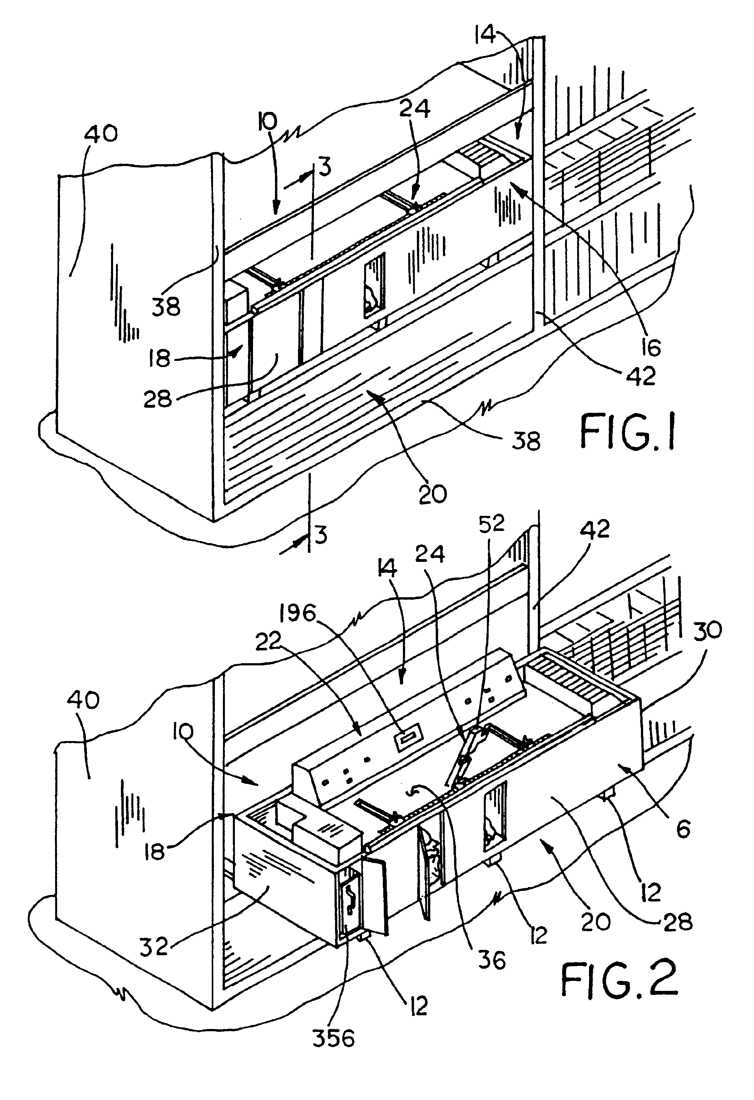
[0051]An apparatus for sizing both blinds and shades for window coverings is generally illustrated in FIGS. 1 and 2. The blind and shade cutting center 10 is slidably movable on rails 12 in and out of a bay 14. The cutting center 10 includes a first cutting station 16 for sizing mini-blinds, pleated shades, and cellular shades. The cutting center further includes a second cutting station 18 for sizing wooden blinds and vertical blinds. The first and second cutting stations 16, 18 are supported by and located on opposing ends of a housing 20. A controller mechanism 22 allows an operator to gain access and to control the first and second cutting stations 16, 18. Further, cutting center 10 includes a center locating and measuring system 24 to position the blinds and shades to be sized.

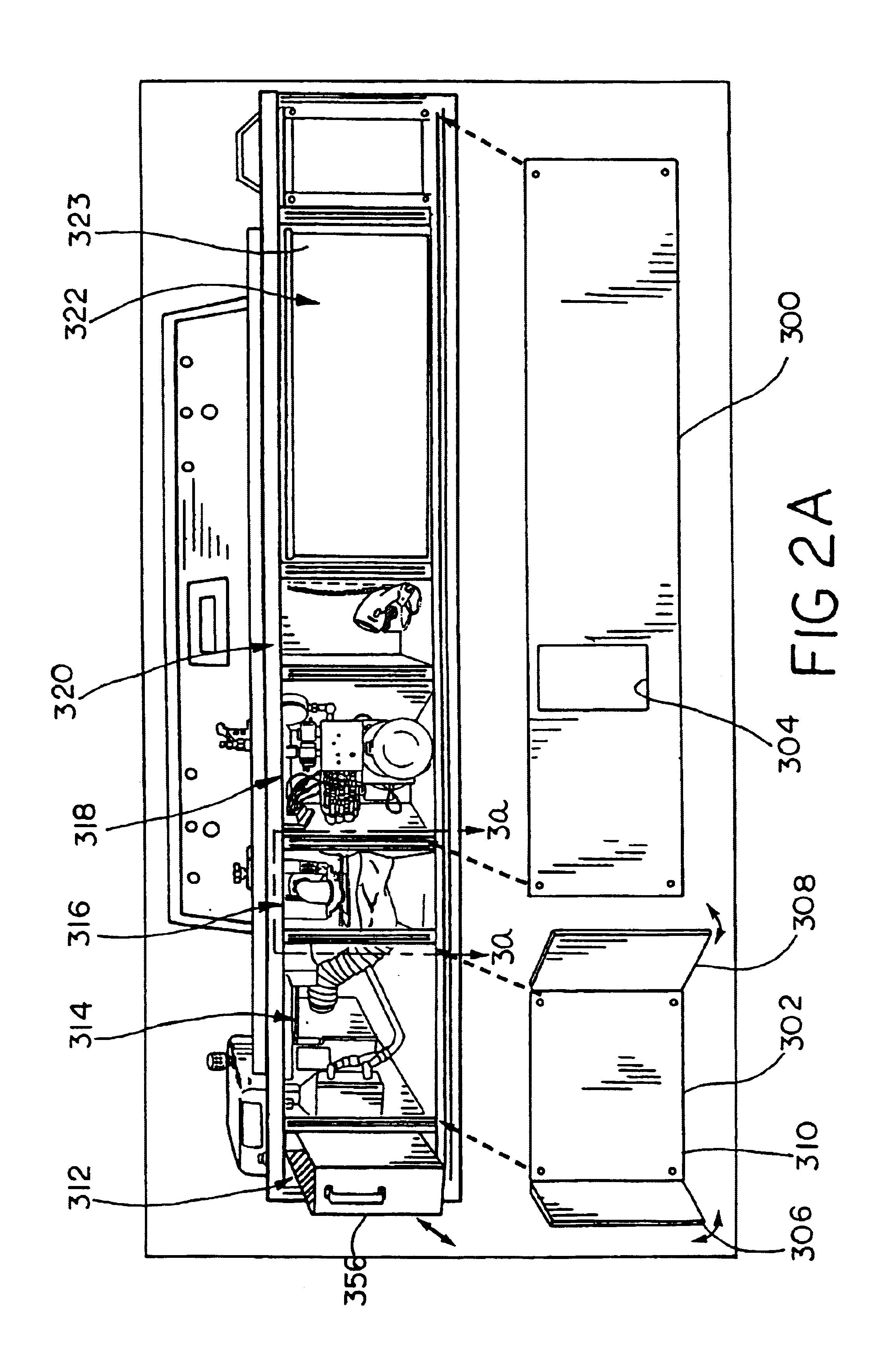
[0052]Referring to FIGS. 2, 2a, and 3 the housing 20 of the cutting center 10 includes a bottom 26, a front wall 28, a first and second side wall 30, 32, a rear wall 34, and a top working surface 36. The ...


PUM

PropertyMeasurementUnit
Sizeaaaaaaaaaa

Abstract

A method and apparatus for sizing window coverings slidably extendable from a bay into an aisle of a retail outlet. The method includes the steps of locating the center of the window covering relative to a cutting station utilizing a half scale for removing a portion of the window covering from each of its ends.

Description

FIELD OF THE INVENTION[0001]The present invention relates generally to the field of window covering sizing machines and more particularly to a blind and shade cutting center.BACKGROUND OF THE INVENTION[0002]Mass retail merchandisers sell a large number of window coverings directly to consumers. Standard sized window coverings are sized to a consumer's specifications while the consumer waits. The apparatus employed to size the various window coverings should be both easy to use by an employee of a retail outlet and should not require an extensive training period.[0003]Additionally, the floor space that the cutting apparatus requires should fit within the existing structure and layout of the retail outlet. Further, the cutting apparatus ideally should size a number of different types of window coverings, such as metal or vinyl mini-blinds, vertical blinds, pleated shades, and cellular shades.[0004]Various attempts have been made to integrate various window covering cutting mechanisms ...

Claims


Application Information

Patent Timeline
IPC IPC(8): B26D7/01B23D23/00E06B9/266
CPCB23D23/00E06B9/266B26D7/01Y10T83/9486Y10T83/95Y10T83/9483Y10T83/412Y10T83/9447
Inventor CAPUTO, THOMAS A.SCHWARTZ, DAVID A.
Owner HUNTER DOUGLAS INDS SWITZERLAND
Why Eureka
Try Eureka