Trampoline system

a trampoline and system technology, applied in the field of trampoline systems, can solve the problems of many on-bed trampoline injuries, many devices that do not directly address injuries, and many injuries on-bed trampoline injuries, so as to reduce the quantity and severity of on-bed injuries

Inactive Publication Date: 2006-06-13
PUBLICOVER MARK W
View PDF6 Cites 15 Cited by
  • Summary
  • Abstract
  • Description
  • Claims
  • Application Information

AI Technical Summary

Benefits of technology

[0004]One approach to reducing trampoline injuries has been to form a wall around the perimeter of a trampoline bed so that when a jumper lands too near the edge, the wall prevents the jumper from falling off. Examples are shown in U.S. Pat. Nos. 5,399,132 and 6,053,845. However, these devices do not directly address injuries that result when users impact the rebounding surface incorrectly or while in an awkward position. A second approach, the use of a harness (worn by the jumper) suspended by elastic cords above the rebounding surface, is an effective way to reduce on-bed, or rebound surface impact injuries. However, such harnesses are designed for safely teaching users advanced acrobatics on high-performance competition trampolines by trained professionals, making them largely inappropriate for low-performance backyard trampolines that are used almost entirely for basic jumping activities and not for advanced acrobatics.
[0007]There thus remains a need to significantly reduce the quantity and severity of the on-bed injuries that result from these playful activities.

Problems solved by technology

However, thousands of injuries have resulted when persons jumping on a trampoline have landed on the rebounding surface while in an awkward or incorrect body position.
However, these devices do not directly address injuries that result when users impact the rebounding surface incorrectly or while in an awkward position.
However, such harnesses are designed for safely teaching users advanced acrobatics on high-performance competition trampolines by trained professionals, making them largely inappropriate for low-performance backyard trampolines that are used almost entirely for basic jumping activities and not for advanced acrobatics.
For instance, many on-bed backyard trampoline injuries occur when multiple jumpers are using the trampoline at the same time as reported in the NEISS data compiled by the CPSC.
Unfortunately, these unstructured trampoline activities can generate on-bed injuries when jumpers land on the rebounding surface in an awkward body position or when a jumper lands on a trampoline bed that has been preloaded with the energy from other jumper impacts.

Method used


Image

  • Trampoline system
  • Trampoline system
  • Trampoline system

Examples


Embodiment Construction

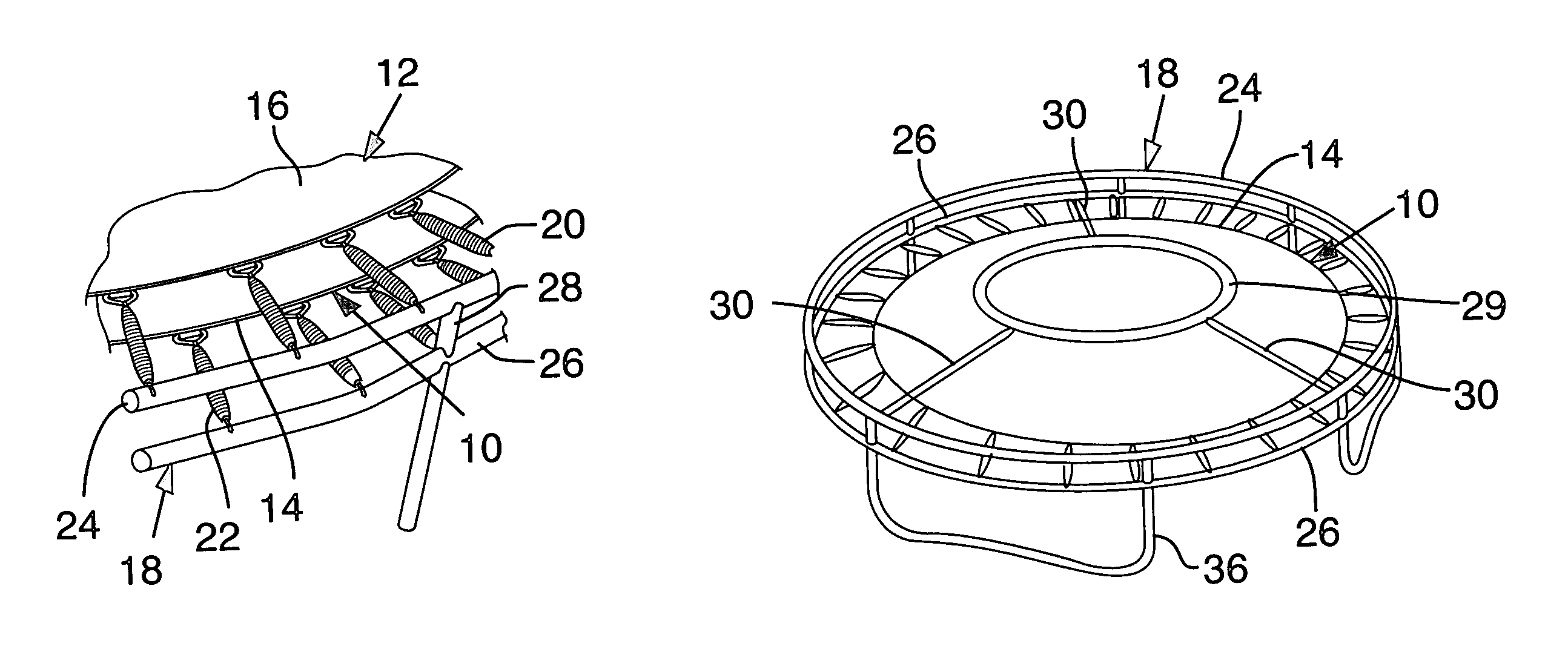
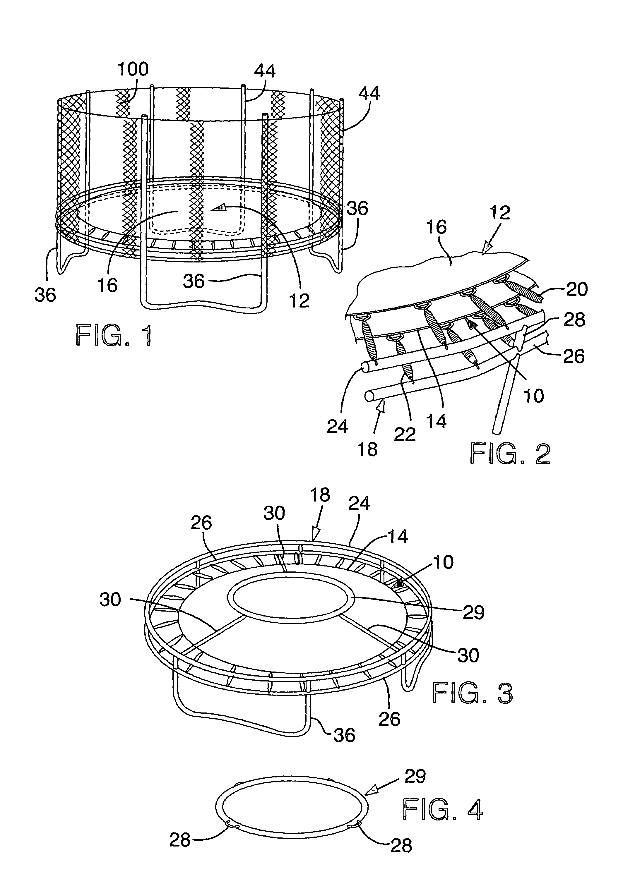
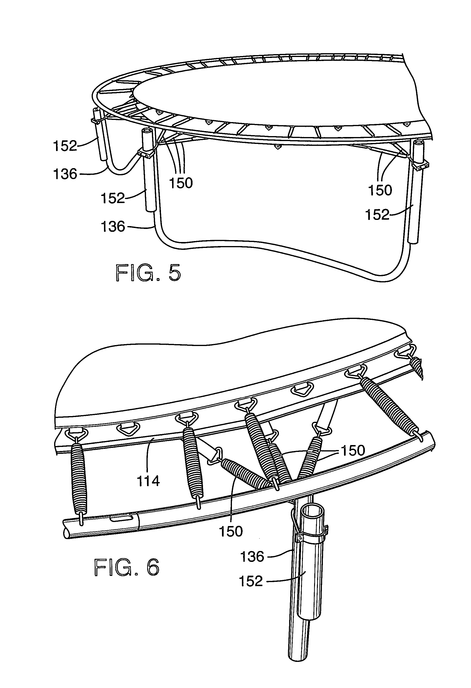
[0015]The drawbacks of prior systems are overcome by the use of a trampoline system that employs one or more resilient members 10 located below the rebounding bed 12 of a trampoline. A resilient member 10 is located at a position selected so that the bed 12 depresses the resilient member 10 when the bed is sufficiently depressed by a person jumping on the bed.

[0016]Such a trampoline system is effective at reducing on-bed injuries that result from multiple jumpers and awkward landings. For instance, many injuries occur when multiple users are jumping asynchronously, a first jumper deflects the bed and loads springs with the energy from his fall and now a second jumper lands on the bed in an awkward position. At this point in time, the bed is highly tensioned (unforgiving) and has just begun moving rapidly upward, recycling the energy loaded into the springs by the first jumpers impact with the bed. In this case a bed / resilient member system can be used to significantly reduce the imp...


PUM


Abstract

A trampoline system has a rebounding bed and a resilient member located below the bed at such a position that the bed depresses the resilient member when the bed is sufficiently depressed by a person jumping on the bed. The presence of the resilient member makes it easy tune the system to adjust the performance of the trampoline and to minimize impacts on a jumper and thereby reduce the likelihood of bed-impact injuries.

Description

CROSS REFERENCE TO RELATED APPLICATION[0001]This is a continuation of application Ser. No. 10 / 240,387 filed Sep. 27, 2002 now U.S. Pat. No. 6,846,271, which is the National Stage of International Application No. PCT / US01 / 41736, filed Aug. 14, 2001, which claims the benefit of Provisional Application No. 60 / 225,326, filed Aug. 14, 2000, all of which prior applications are incorporated herein by reference.BACKGROUND AND SUMMARY[0002]The present invention concerns systems for use with trampolines to protect trampoline users from injury.[0003]Trampolines are used for a variety of athletic and recreational purposes. However, thousands of injuries have resulted when persons jumping on a trampoline have landed on the rebounding surface while in an awkward or incorrect body position. These “on-bed” injuries, according to some medical studies, represent the majority of trampoline-related emergency room visits. The U.S. Consumer Products Safety Commission (CPSC) reports that in 1999 approxima...

Claims


Application Information

Patent Timeline
Patent Type & Authority Patents(United States)
IPC IPC(8): A63B5/11
CPCA63B5/11A63B2208/12A63B71/022A63B21/023
Inventor PUBLICOVER, MARK W.
Owner PUBLICOVER MARK W
Why Eureka
Try Eureka