Intraluminal lining

a technology of intraluminal prosthesis and lining, which is applied in the field of intraluminal prosthesis, can solve the problems of high risk of infection and/or rejection, difficult to effectively secure the endoprosthesis, and difficult to achieve the effect of mechanical securemen

Inactive Publication Date: 2006-06-13
LIFESHIELD SCI
View PDF6 Cites 142 Cited by
  • Summary
  • Abstract
  • Description
  • Claims
  • Application Information

AI Technical Summary

Benefits of technology

[0008]It is an object of the present invention to provide an implantable prosthesis capable of effective securement within a body lumen.
[0009]It is a further object of the present invention to provide an implantable prosthesis which does not inhibit normal flow through the lumen.
[0016]In a further embodiment of the present invention, a method of adhering an intraluminal liner to a venal wall is provided. The method includes providing a prosthesis including an intraluminal liner having a biocompatible adhesive active in an intraluminal environment disposed on an exterior surface thereof; delivering the prosthesis to an area of implantation; and expanding the prosthesis so as to cause the adhesive to contact an interior surface of the venal wall, thereby causing the adhesive to bond the prosthesis to the venal wall.

Problems solved by technology

Such replacement procedures, however, generally involve invasive surgery, resulting in extensive recovery and high risk of infection and / or rejection.
As can be appreciated, such mechanical securement means cannot effectively secure an endoprosthesis such as a graft continuously along the entire length thereof.
Such mechanical securement can result in unsecured portions of the graft, thus resulting in gaps between the graft wall and the intraluminal wall of the vessel.
Such gaps can result in an increased amount of cell growth necessary to anchor the prosthesis in place.
Further, such mechanical securement can result in a bulky structure present within the lumen, which can inhibit normal flow through the lumen, and create a site for occlusion within the vessel.
As can be appreciated, however, PTFE is difficult to adhere to vessel walls due to these inert properties.

Method used


Image

  • Intraluminal lining
  • Intraluminal lining
  • Intraluminal lining

Examples


Embodiment Construction

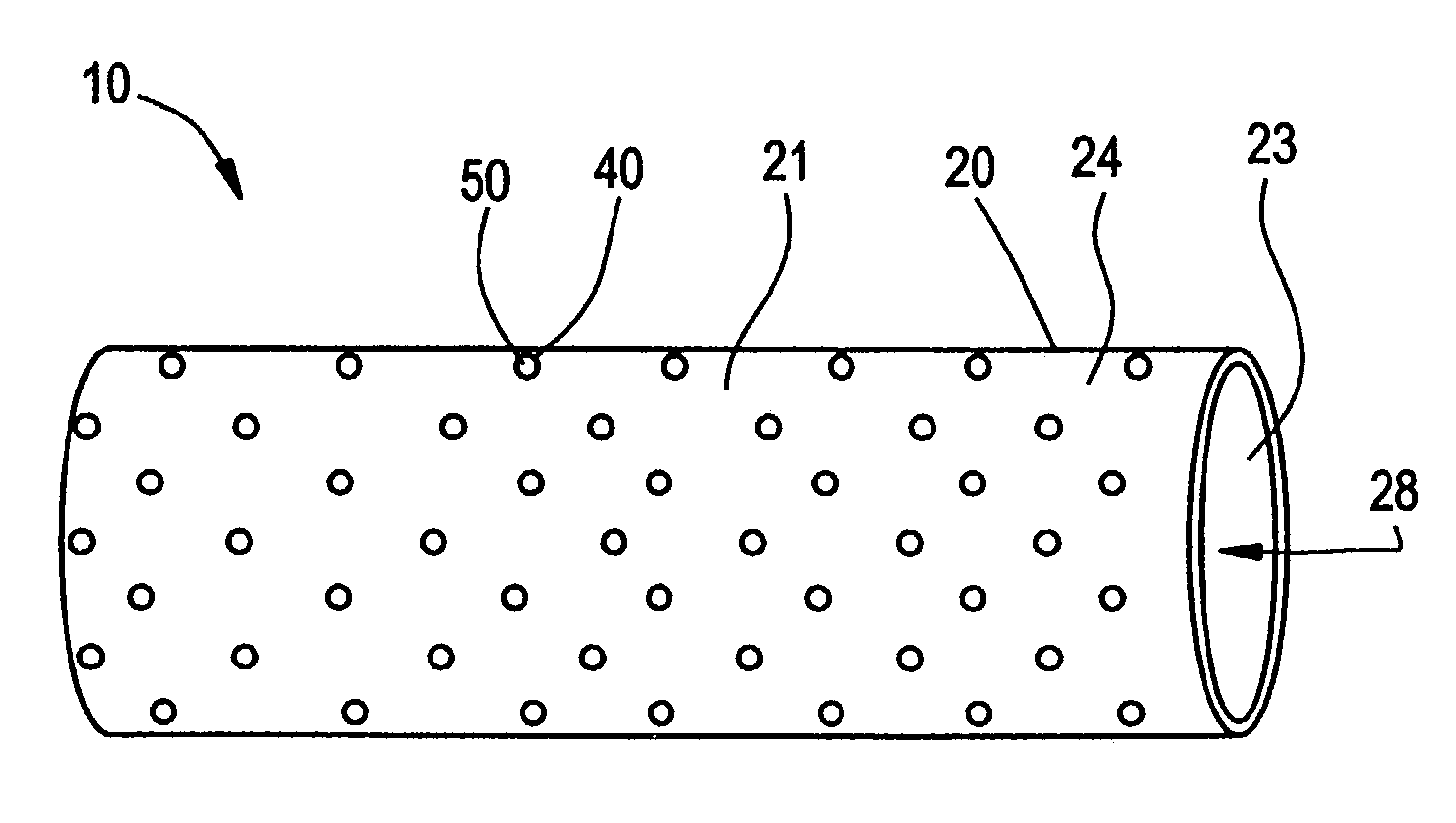
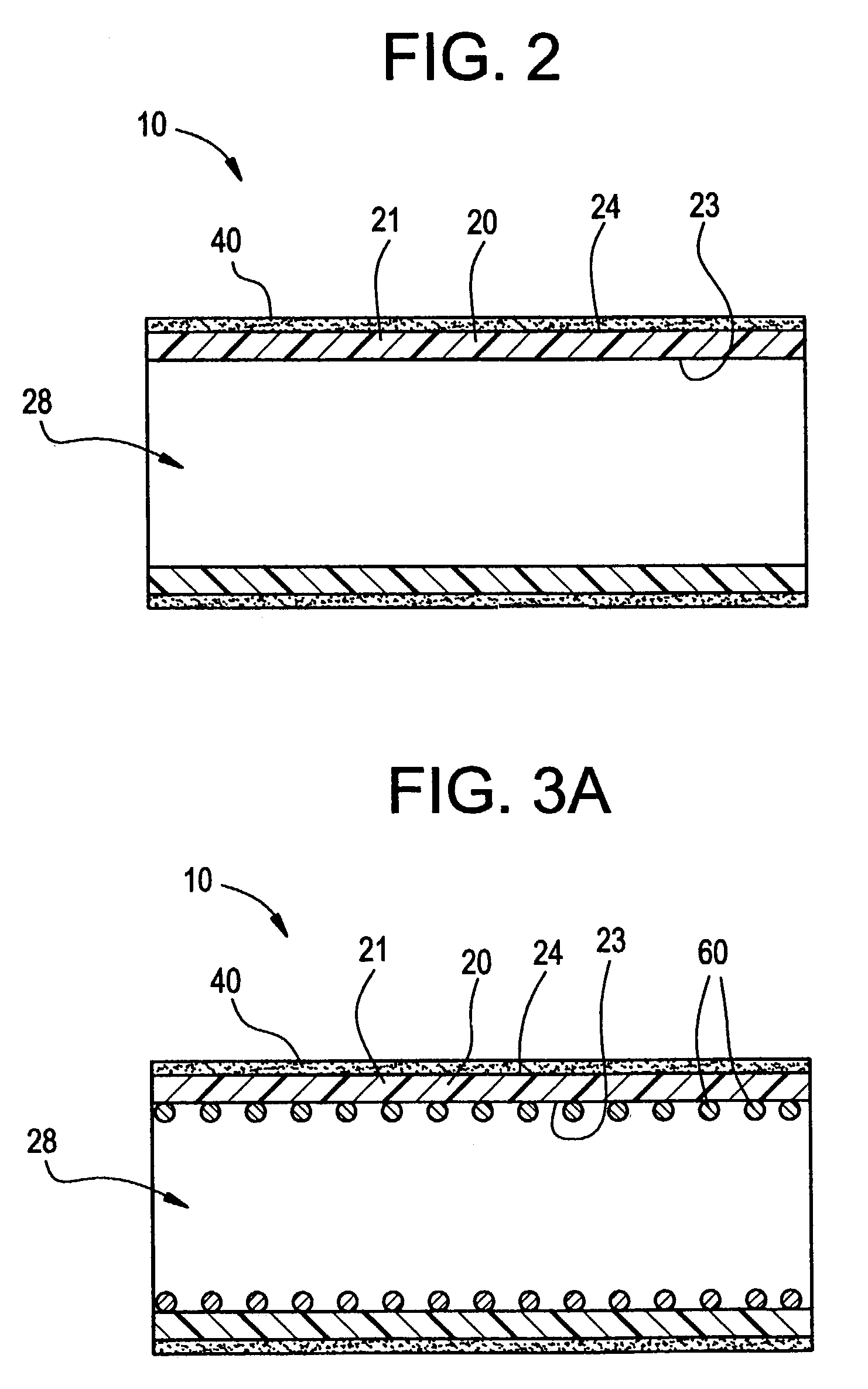
[0023]The present invention is directed to a prosthesis for implantation within a body lumen. The prosthesis includes a biocompatible elongate intraluminal liner in the form of a graft, with a biocompatible adhesive being disposed on an exterior surface of the graft. The adhesive is active in an intraluminal environment so as to bond the exterior surface of the graft to an intraluminal surface of the body lumen, such as the interior of a blood vessel. Typically, implantable prostheses such as vascular grafts are held in place within a body lumen by suturing or by anchoring with a mechanical device such as a stent. With the present invention, prostheses can be properly anchored in place within a body lumen and maintain the vessel from occluding without the need for such suturing or mechanical supports, thus reducing the possibility of thrombus formation and neo-intimal hyperplasia.

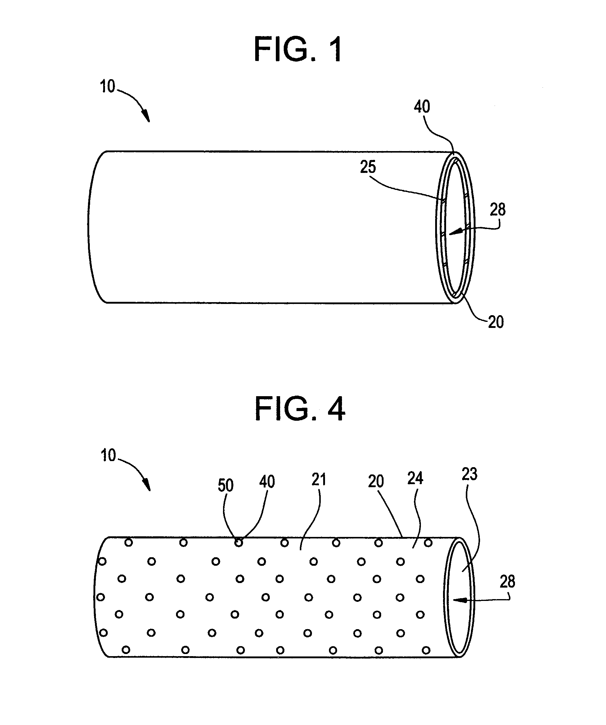
[0024]With reference to the drawings, FIG. 1 depicts a prosthesis according to the present invention. Pr...


PUM

PropertyMeasurementUnit
biocompatibleaaaaaaaaaa
pressureaaaaaaaaaa
adhesiveaaaaaaaaaa

Abstract

The present invention is directed to a prosthesis for implantation within a body lumen. The prosthesis includes a biocompatible elongate intraluminal liner in the form of a graft, with a biocompatible adhesive being disposed on an exterior surface of the graft. The adhesive is active in an intraluminal environment so as to bond the exterior surface of the graft to an intraluminal surface of said body lumen, such as the interior of a blood vessel.

Description

[0001]This application is a continuation of application Ser. No. 09 / 957,618, filed on Sep. 20, 2001, which is now U.S. Pat. No. 6,514,283, and which is a continuation of Ser. No. 09 / 283,556, filed on Apr. 1, 1999, which is now U.S. Pat. No. 6,312,457.FIELD OF THE INVENTION[0002]The present invention relates to the field of intraluminal prostheses. More specifically, the present invention is directed to an intraluminal prosthesis which is adhesively bonded to the interior wall of a body conduit.BACKGROUND OF THE INVENTION[0003]The use of tubular devices or conduits is well known in the repair or replacement of damaged or diseased lumens within the body. For example, tubular conduits are used to repair lumens such as in the esophagus and colon areas, and in particular, prostheses are used in the vascular system to repair, buttress or replace a weakened section of the vessel. It is well known in the field of vascular surgery to surgically replace a portion of a vessel with an endoprost...

Claims


Application Information

Patent Timeline
Patent Type & Authority Patents(United States)
IPC IPC(8): A61F2/06A61L27/00A61L27/34
CPCA61F2/06A61F2/07A61L27/34A61F2002/072A61F2220/005A61F2210/0004A61F2002/075
Inventor DIMATTEO, KRISTIANRAVENSCROFT, ADRIAN
Owner LIFESHIELD SCI
Why Eureka
Try Eureka