
Static electric power converter for modulating electric power exchanged between at least a voltage source and a current source

Inactive Publication Date: 2006-06-13
CENT NAT DE LA RECHERCHE SCI
View PDF4 Cites 0 Cited by
  • Summary
  • Abstract
  • Description
  • Claims
  • Application Information

AI Technical Summary

Benefits of technology

[0030]All these facts mean that the technical effects of the invention show themselves in terms of operational safety and simplification of the static electrical energy converters. The economic effects are to be found in better availability of equipment and cheaper static converters.
[0031]Moreover, the introduction of the automatic conversion enables switches with automatic switching to be combined with switches with controlled switching, of identical types of materials such as superconductors, photoconductors, with a view to the realisation of static conversion circuits.
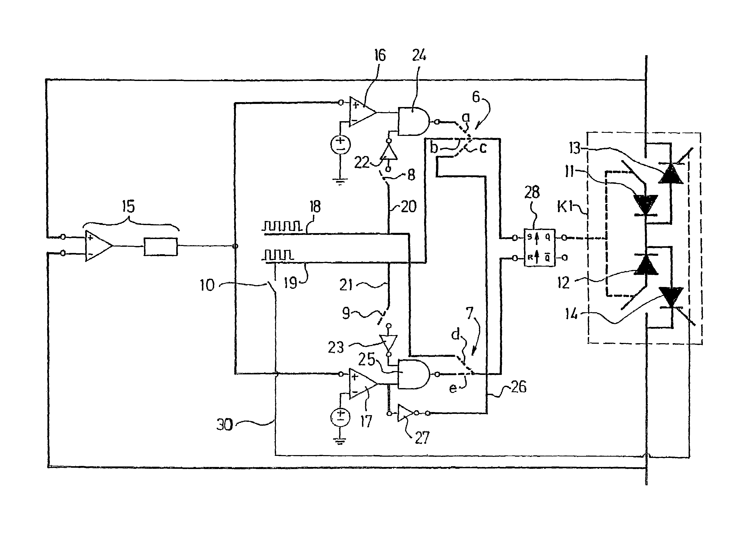
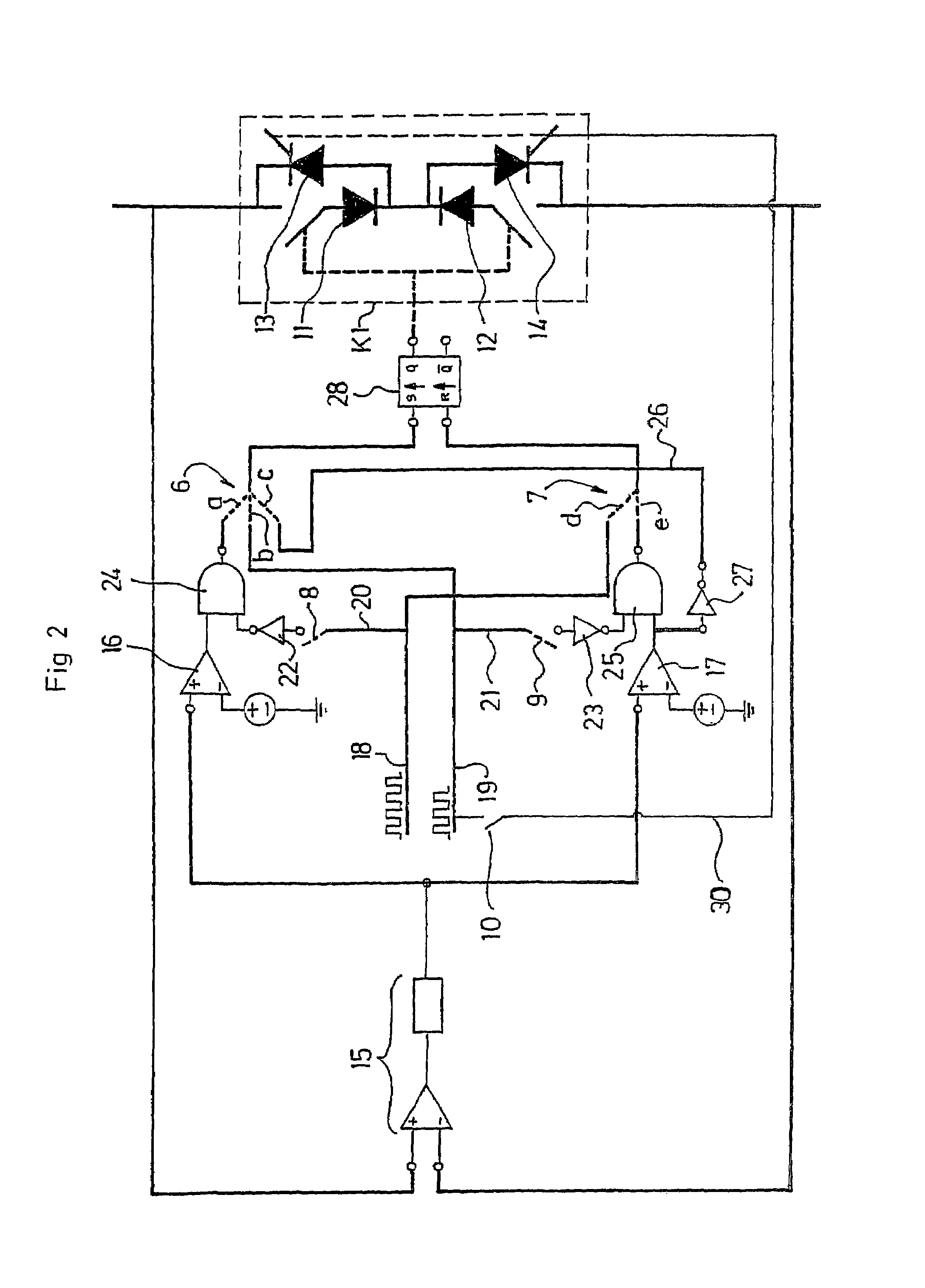
[0032]According to an advantageous embodiment, the static converter as claimed by the invention has, for each switch with automatic switching, with a view to providing each of the automatic changes of state of said switch:
[0033]a differential voltage detector connected in parallel to the output electrodes of said switch and designed to deliver a signal representing the absolute value of the voltage at the terminals of said electrodes,
[0034]a voltage comparator connected to the voltage detector and designed to deliver a change-of-state signal, at the opening or at the closing, when the predefined voltage threshold is reached,
[0035]and switching means connected to the voltage comparator and designed to bring about a change of state in the switch, providing switching at the opening or at the closing on reception of the change-of-state signal.

Problems solved by technology

Moreover, the relationships between the switching mechanisms of the switches in a stage results from the laws of the nodes and the links relative to this same stage, and the lossy nature of the switches.
Consequently, the switches of present-day static converters offer a limited number of possible switching mechanisms and the designers are thus forced to resort to multiple combinations of electrical switching stages and to management of the more or less complex controlled switching operations using sensors.
They are therefore composed of specific elements added to the switches dedicated to the switching and which result in an increase in the complexity and cost of the electric power conversion circuits.
Another drawback lies in the fact that present-day static converters are not able to use superconductive materials, photoconductors, due to the fact that these materials are unable to have spontaneous transitions.

Method used


Image

  • Static electric power converter for modulating electric power exchanged between at least a voltage source and a current source
  • Static electric power converter for modulating electric power exchanged between at least a voltage source and a current source
  • Static electric power converter for modulating electric power exchanged between at least a voltage source and a current source

Examples


Embodiment Construction

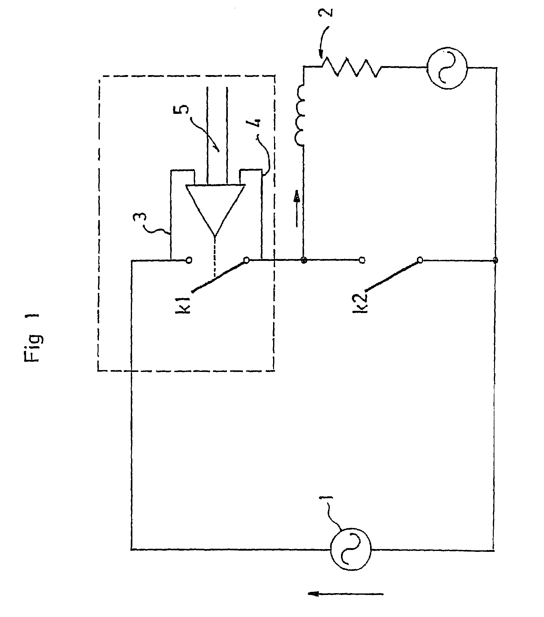
[0068]The basic conversion stage shown in FIG. 1 comprises, in a conventional manner, an electrical voltage source 1, a current source 2, and two static switches with switching K1, K2, star-connected to the voltage source 1, with the common point of the star connected to the current source 2.

[0069]As claimed by the invention, at least one of the static switches in the example K1 is a switch equipped with two output electrodes 3, 4, of which at least one of the changes of state is automatic and is operated exclusively at a predefined threshold, other than zero, when the absolute value of said voltage rises.

[0070]Furthermore, this switch K1 is connected to a switching mechanism 5 capable of allowing five different switching modes of said switch to be controlled, that is to say:[0071]controlled closing—automatic opening,[0072]spontaneous closing—automatic opening[0073]automatic closing—controlled opening[0074]automatic closing—spontaneous opening[0075]automatic closing—automatic openin...


PUM


Abstract

A static electrical energy converter modulates the electrical energy exchanged between at least two electrical sources. The converter includes at least one electrical voltage source, one current source and at least one electrical switching stage, each switching stage having at least two static switches (k1) star-connected to the voltage source or voltage sources, with the common point of the star connected to the current source, and the current source being connected back to the voltage source or sources. At least one of the static switches (k1) of at least one switching stage is a switch provided with two output electrodes, of which at least one change of state (providing switching at the opening or at the closing) is automatic and is operated exclusively at a predefined voltage threshold other than zero when the absolute value of the voltage increases.

Description

BACKGROUND OF THE INVENTION[0001]The invention concerns a static electrical energy converter intended to modulate the electrical energy exchanged between at least two electrical sources, comprising at least one electrical voltage source, one current source and at least one electrical switching stage, each switching stage having at least two static switches star-connected to the voltage source or voltage sources, with the common point of the star connected to the current source, and said current source being connected back to the voltage source or sources.[0002]The electrical switching stages depend on the presence of at least two switches intended to modulate the electrical energy exchanged between at least two electrical sources. These switches are in an electrically “open” or “closed” state and the modulation consists in alternately opening and closing these switches for variable periods.DESCRIPTION OF THE RELATED ART[0003]At the present time, the changes of state, or switching op...

Claims


Application Information

Patent Timeline
IPC IPC(8): G05F1/40G05F1/45H02M1/00H02M3/335H02M5/293
CPCH02M1/00H02M3/33592Y02B70/1475Y02B70/10
Inventor RICHARDEAU, FREDERICFOCH, HENRI
Owner CENT NAT DE LA RECHERCHE SCI
Learn More