
Switch and bridged network

a bridge network and switch technology, applied in the field of switch and bridge network, can solve the problems of not being economical to use unused paths, and the inability to use said spanning tree,

Inactive Publication Date: 2006-06-13
FUJITSU LTD
View PDF2 Cites 23 Cited by
  • Summary
  • Abstract
  • Description
  • Claims
  • Application Information

AI Technical Summary

Benefits of technology

The present invention provides a switch that supports a multiple spanning tree protocol and automatically selects an optimum spanning tree. The switch includes a table with a default spanning tree and a transceiver for transmitting an inquiry frame to a destination terminal through the default spanning tree and receiving inquiry response frames from all spanning trees connected to the switch. An optimum spanning tree is selected based on information in the inquiry response frames. The switch can be used in a bridged network formed of multiple switches. The technical effect of the invention is to improve network efficiency and reliability by automatically selecting an optimum spanning tree.

Problems solved by technology

It is not economical that unused paths exist although the single spanning tree has redundant paths.
As a result, there has been a problem that even if there is an optimum spanning tree (for example, a spanning tree with a smaller hop count, etc.), the said spanning tree cannot be used.

Method used


Image

  • Switch and bridged network
  • Switch and bridged network
  • Switch and bridged network

Examples


Embodiment Construction

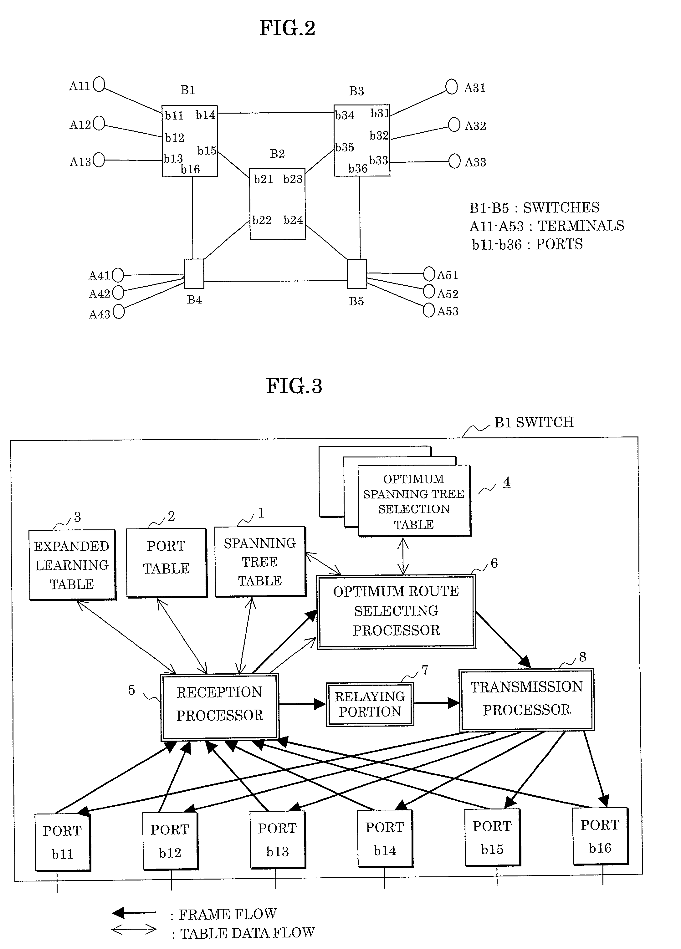
[0049]FIG. 2 shows the bridged network shown in FIGS. 1A–1C more specifically, where the switch B1 having ports b11–b16, the switch B2 having ports b21–b24, and the switch B3 having ports b31–b36 are especially illustrated.

[0050]In the switch B1, the ports b11–b13 form edge ports since being connected to the terminals A11–A13, and the ports b14–b16 form trunk ports since being connected to the side of the switches.

[0051]Also in the switch B2, all of the ports b21–b24 form the trunk ports since being connected to the switches. In the switch B3, the ports b31–b33 form the edge ports since being connected to the terminals A31–A33, and the ports b34–b36 form the trunk ports since being connected to the side of the switches.

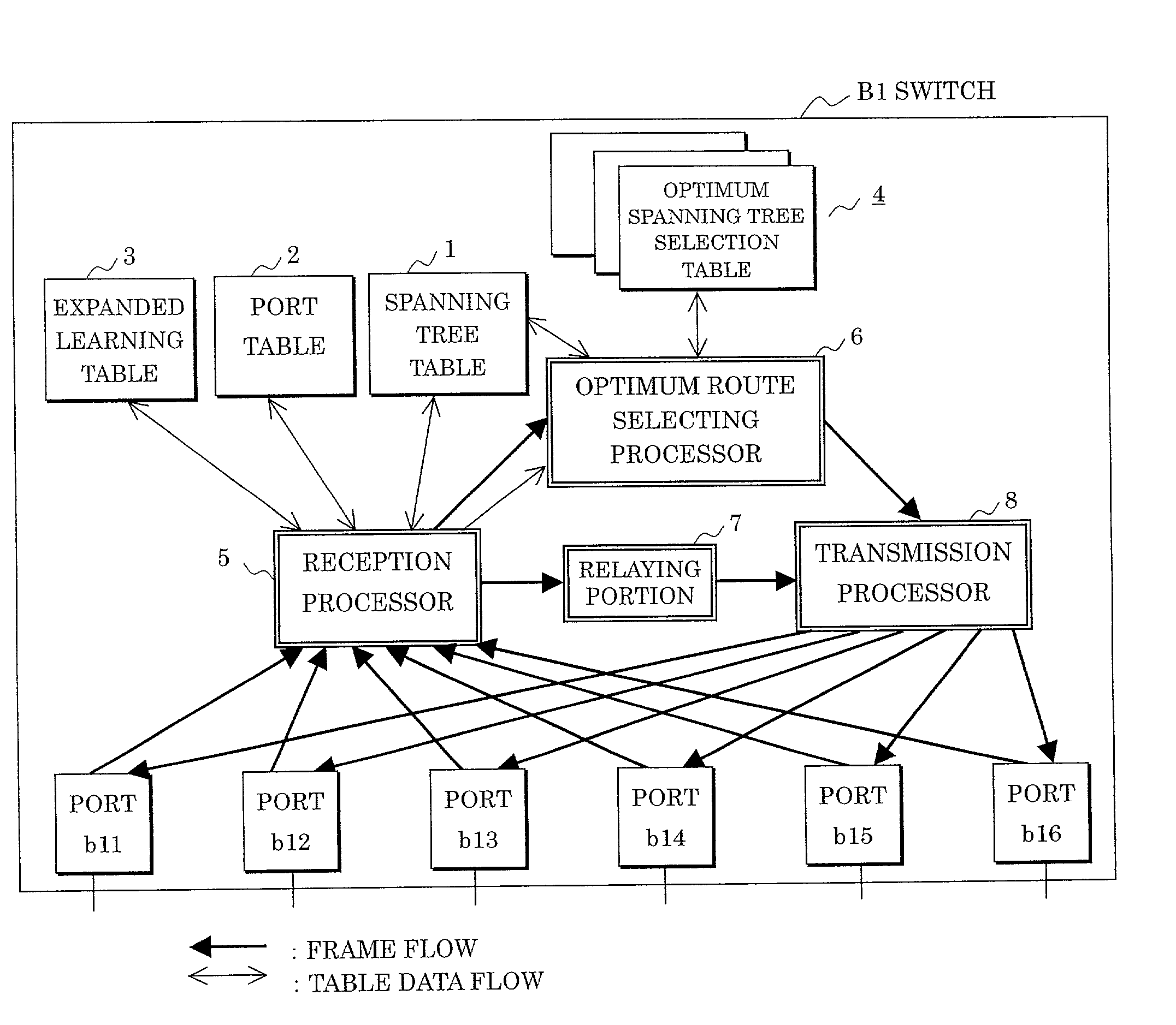
[0052]FIG. 3 shows an arrangement of each of the switches B1–B5 forming such a bridged network. The arrangement of the switch B1 is specifically shown for this example.

[0053]In this switch arrangement, a spanning tree table 1, a port table 2, an expanded learning tabl...


PUM


Abstract

In a switch supporting a multiple spanning tree protocol and a bridged network formed of such a switch, the switch includes a default spanning tree in a multiple spanning tree, transmits, upon receipt of a frame having an individual destination address from a terminal side, an inquiry frame to a destination terminal of the individual destination address through the default spanning tree, transmits inquiry response frames to all of the spanning trees in the multiple spanning tree if the destination terminal is connected to the switch, and selects an optimum spanning tree based on information in the inquiry response frames from all of the spanning trees.

Description

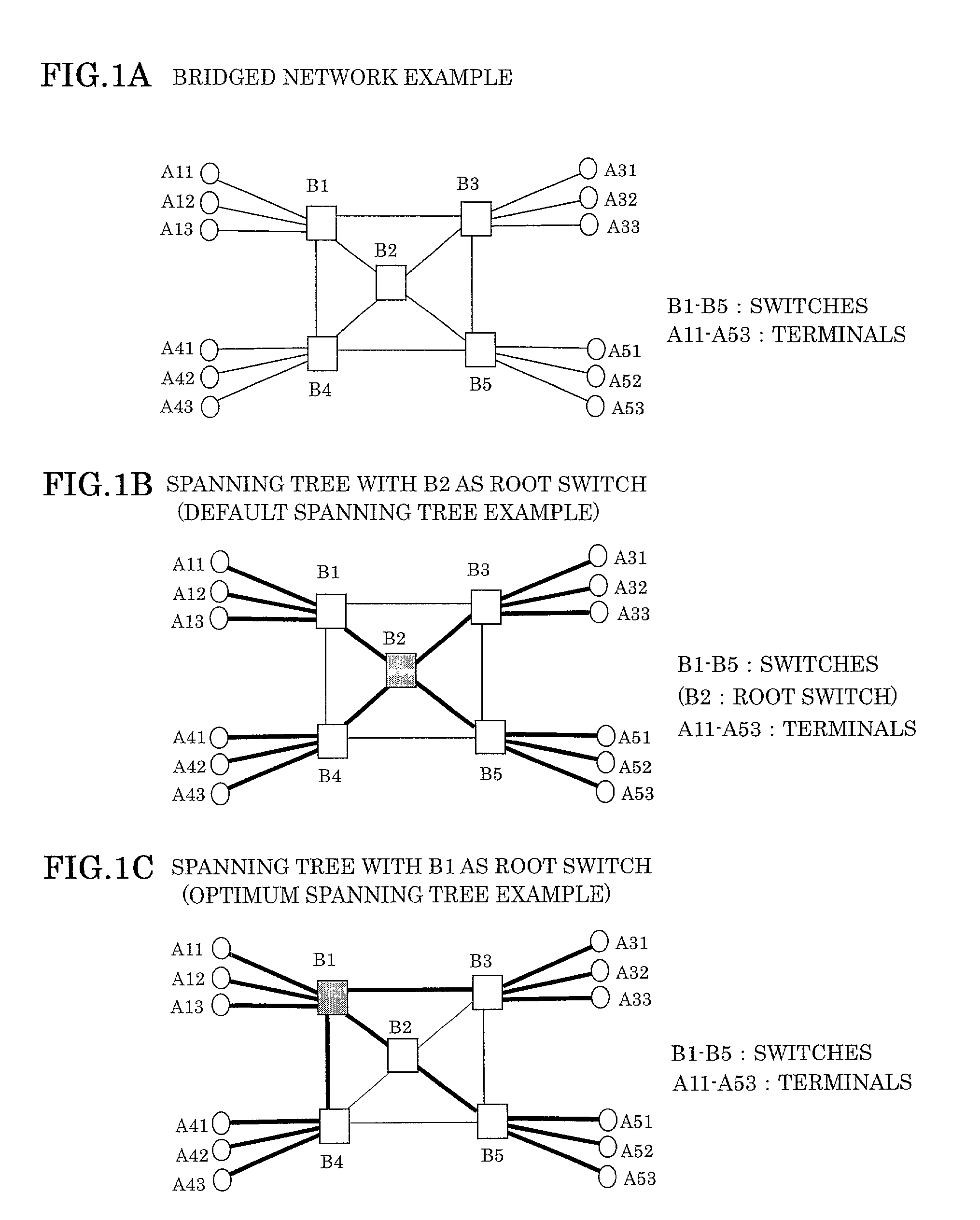
BACKGROUND OF THE INVENTION[0001]1. Field of the Invention[0002]The present invention relates to a switch and a bridged network, and in particular to a switch supporting a multiple spanning tree protocol and a bridged network formed of such a switch.[0003]2. Description of the Related Art[0004]A bridged network, as shown in FIG. 1A for example, is formed of switches B1–B5 provided with a bridge function for switching a transmission frame according to a MAC (Media Access Control) destination address, terminals A11–A13 connected to the switch B1, terminals A31–A33 connected to the switch B3, terminals A41–A43 connected to the switch B4, and terminals A51–A53 connected to the switch B5. The switches B1–B5 form loops. A switch and a terminal as well as a switch and another switch are connected with an LAN (Local Area Network).[0005]In such a bridged network, a frame is relayed along a communication path (spanning tree) formed by a spanning tree protocol (STP) standardized by IEEE802.1D....

Claims


Application Information

Patent Timeline
Patent Type & Authority Patents(United States)
IPC IPC(8): H04L12/28H04L12/46
CPCH04L45/02H04L45/48H04L45/28H04L45/484
Inventor AMBE, MICHIKO
Owner FUJITSU LTD
Learn More