
Transmission power control apparatus

Inactive Publication Date: 2006-06-13
FUJITSU LTD
View PDF30 Cites 58 Cited by
  • Summary
  • Abstract
  • Description
  • Claims
  • Application Information

AI Technical Summary

Benefits of technology

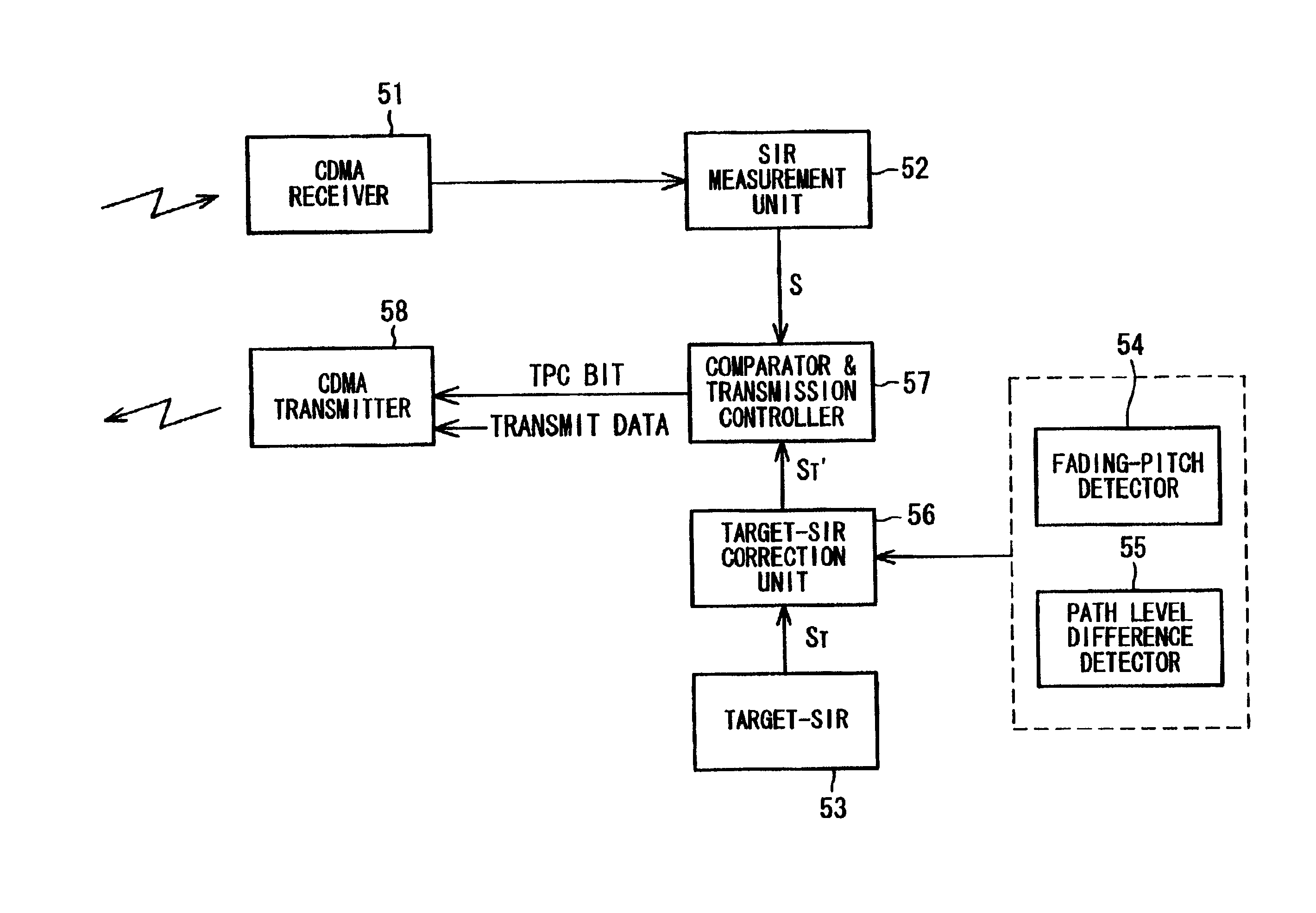
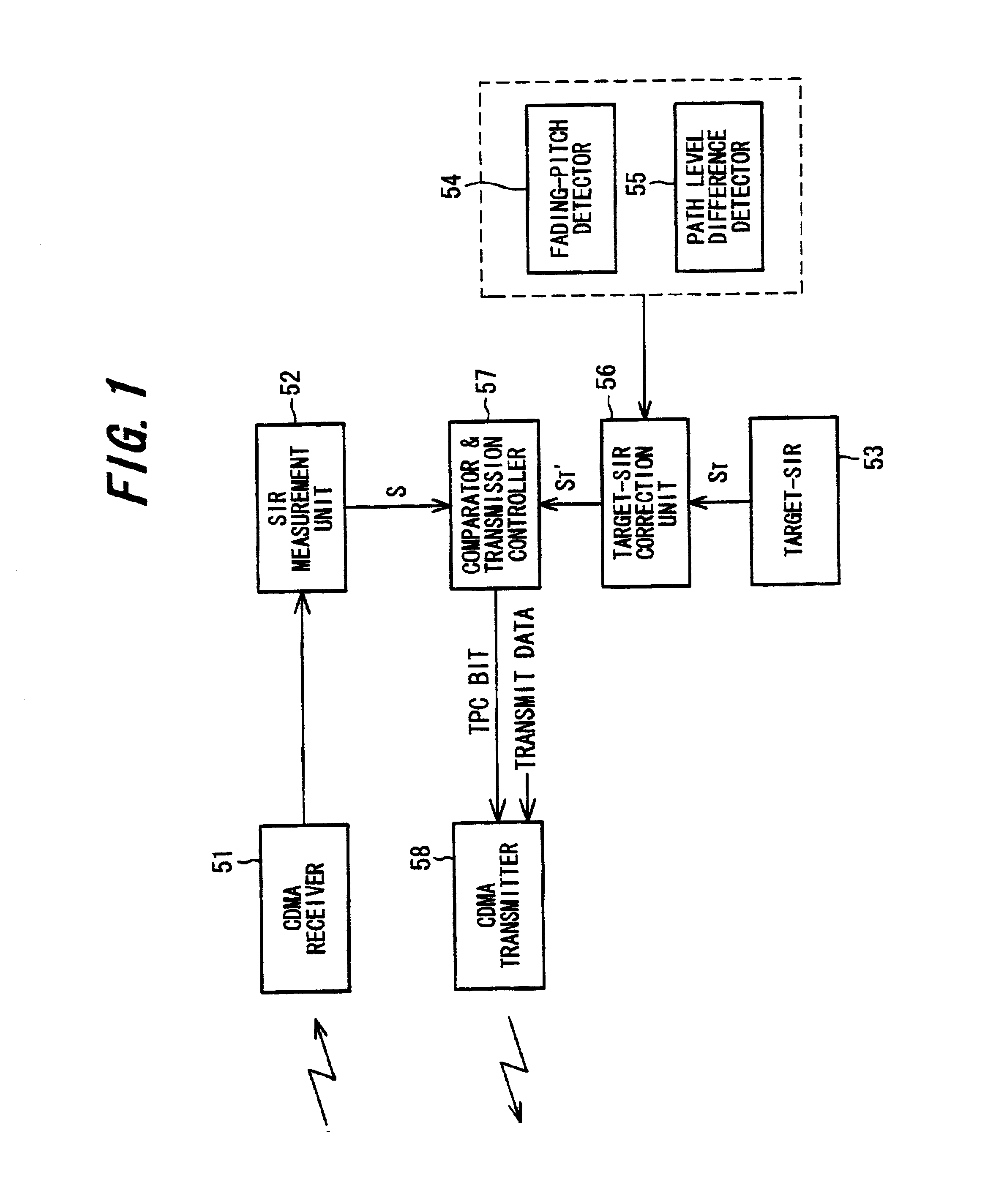
[0015]Accordingly, an object of the present invention is to enlarge the target SIR so that the desired BER can be maintained when the rate of change in fading (the fading pitch) increases.
[0016]Another object of the present invention is to control the target SIR, thereby making it possible to maintain the desired BER, based upon level differences between signals that arrive via the paths of multiple paths.
[0017]Another object of the present invention is to control the target SIR, thereby making it possible to maintain the desired BER, based upon a combination of rate of change in fading and level differences between signals that arrive via each path.

Problems solved by technology

Consequently, in a case where mobile stations transmit to a base station, a so-called near-far problem occurs.
Specifically, if a mobile station near the base station and a mobile station far from the base station transmit at the same power, the transmission power of the nearby mobile station will be more than necessary and will interfere with transmission from the other mobile station.
However, if the traveling speed of the mobile station varies and the rate of change in fading increases [i.e., if fading pitch (Hz) rises], then transmission power control based upon the TPC bit can no longer follow up the change in fading.
In addition, channel estimation becomes erroneous and BER=10−3 can no longer be maintained.
With conventional transmission power control, a problem which arises is that BER=10−3 can no longer be maintained owing to the number of paths or the level differences between paths.

Method used


Image

  • Transmission power control apparatus
  • Transmission power control apparatus
  • Transmission power control apparatus

Examples


first embodiment

[0084](a) First Embodiment

[0085]FIG. 6 illustrates a first embodiment of transmission power control for correcting a target SIR by a fading pitch detected using a pilot signal.

[0086]A mobile station 100 includes a spread-spectrum modulator 101 for spread-spectrum modulating transmit data using a spreading code conforming to a prescribed channel specified by a base station, and a power amplifier 102 for amplifying a signal, which is input thereto following processing such as quadrature modulation and frequency conversion applied after spread-spectrum modulation, and transmitting the amplified signal to a base station 200 from an antenna.

[0087]The base station 200 subjects the receive signal from the mobile station to a frequency conversion (RF→IF conversion), quadrature detection and AD conversion processing and inputs the AD-converted output to a despreader 201 of a finger conforming to each path of multiple paths. The despreader 201 subjects a delayed signal that arrives via an ass...

second embodiment

[0092](b) Second Embodiment

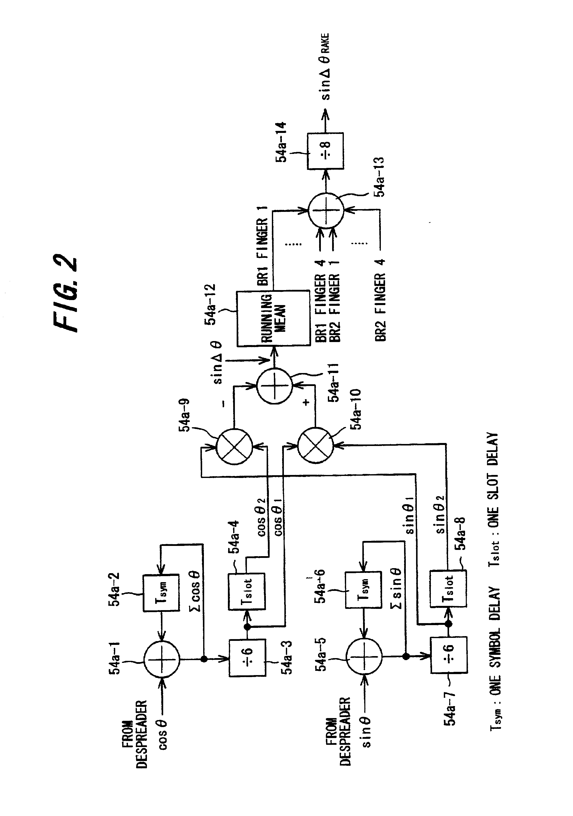
[0093]FIG. 7 illustrates a second embodiment of transmission power control for correcting a target SIR by fading pitch detected using SIR. Components identical with those of the first embodiment shown in FIG. 6 are designated by like reference characters. This embodiment differs in that:[0094](1) Fading pitch is detected by a fading-pitch detection circuit 211, which is shown in FIG. 4, using received SIR.[0095](2) Before the apparatus is placed in operation, fading is varied, fading pitch is measured by the fading-pitch detection circuit 211 and the correction data ΔS of a target SIR for which the desired BER is obtained is found with respect to the fading pitch. This is repeated in similar fashion to obtain the correspondence between a large number of values of fading pitch and the correction data and the correspondence is burned into the ROM 204.

[0096]Transmission power control is carried out in a manner similar to that of the first embodiment.

third embodiment

[0097](c) Third Embodiment

[0098]FIG. 8 illustrates a third embodiment of transmission power control for correcting a target SIR by fading pitch detected using a change in the transmission power control direction of TPC bits. Components identical with those of the first embodiment shown in FIG. 6 are designated by like reference characters. This embodiment differs in that:

[0099](1) Fading pitch is detected by a fading-pitch detection circuit 212, which is shown in FIG. 5, on the basis of a change in direction of power transmission control.

[0100](2) Before the apparatus is placed in operation, fading is varied, fading pitch is measured by the fading-pitch detection circuit 212 and the correction data ΔS of a target SIR for which the desired BER is obtained is found with respect to the fading pitch. This is repeated in similar fashion to obtain the correspondence between a large number of values of fading pitch and the correction data and the correspondence is burned into the ROM 204.

[...


PUM


Abstract

In a transmission power control apparatus for measuring SIR, which is a ratio of a receive signal to an interference signal, and controlling transmission power of a mobile station in such a manner that the measured SIR will agree with a target SIR, a fading detector detects the rate of change in fading, a correction unit corrects the target SIR based upon the rate of change in fading, and a transmission power control command creation unit creates a command for controlling transmission power of the mobile station in such a manner that the measured SIR will agree with the corrected target SIR, and transmits this command. Further, a searcher detects multipath and the levels of signals that arrive via respective ones of the paths, a level-difference calculation unit calculates level differences between the paths, a correction unit corrects the target SIR based upon the level differences between the paths, and a transmission power control command creation unit creates a command for controlling transmission power of the mobile station in such a manner that the measured SIR will agree with the corrected target SIR, and transmits this command.

Description

[0001]This application is a continuation of PCT / JP99 / 05183, filed Sep. 22, 1999, currently pending.BACKGROUND OF THE INVENTION[0002]This invention relates to a transmission power control apparatus of a base station for controlling the transmission power of a mobile station in a CDMA mobile communication system. More particularly, the invention relates to a transmission power control apparatus for obtaining a desired value of BER (Bit Error Rate) by correcting a SIR (target SIR), which is the target of transmission power control, based upon fading pitch or level differences between paths.[0003]Analog schemes were used as modulation schemes for mobile communication in the past but present-day schemes are mainly digital. In general, an analog cellular scheme is referred to as a first-generation scheme, and a digital scheme such as PDC (the Japanese standard), GSM (the European standard), IS54 (the TDMA standard in the USA) and IS95 (the CDMA standard in the USA) is referred to as a sec...

Claims


Application Information

Patent Timeline
IPC IPC(8): H04B7/00H04B1/707H04B7/005H04J13/00H04W52/04H04W52/12H04W52/20H04W52/24H04W52/28H04W88/08H04W88/14
CPCH04W52/12H04W52/24H04W52/283H04W52/20
Inventor NAKAMURA, SATOSHIMINOWA, MORIHIKOKAWAGUCHI, NORIYUKISAWADA, KENSUKEKUBO, TOKUROKIMURA, DAI
Owner FUJITSU LTD
Learn More