Bottom-up/top-down retractable cellular shade

a retractable, bottom-up technology, applied in the direction of sliding/moving grilles, door/window protective devices, curtain suspension devices, etc., can solve problems such as blocking vision and ligh

Inactive Publication Date: 2006-06-20
HUNTER DOUGLAS INC
View PDF22 Cites 72 Cited by
  • Summary
  • Abstract
  • Description
  • Claims
  • Application Information

AI Technical Summary

Benefits of technology

[0015]It will be appreciated that the covering of the present invention is a bottom-up/top-down covering with the bottom rail and intermediate rail being movably positionable anywhere in between thei...

Problems solved by technology

One disadvantage with this type of cellular covering resides in the fact th...

Method used


Image

  • Bottom-up/top-down retractable cellular shade
  • Bottom-up/top-down retractable cellular shade
  • Bottom-up/top-down retractable cellular shade

Examples


Embodiment Construction

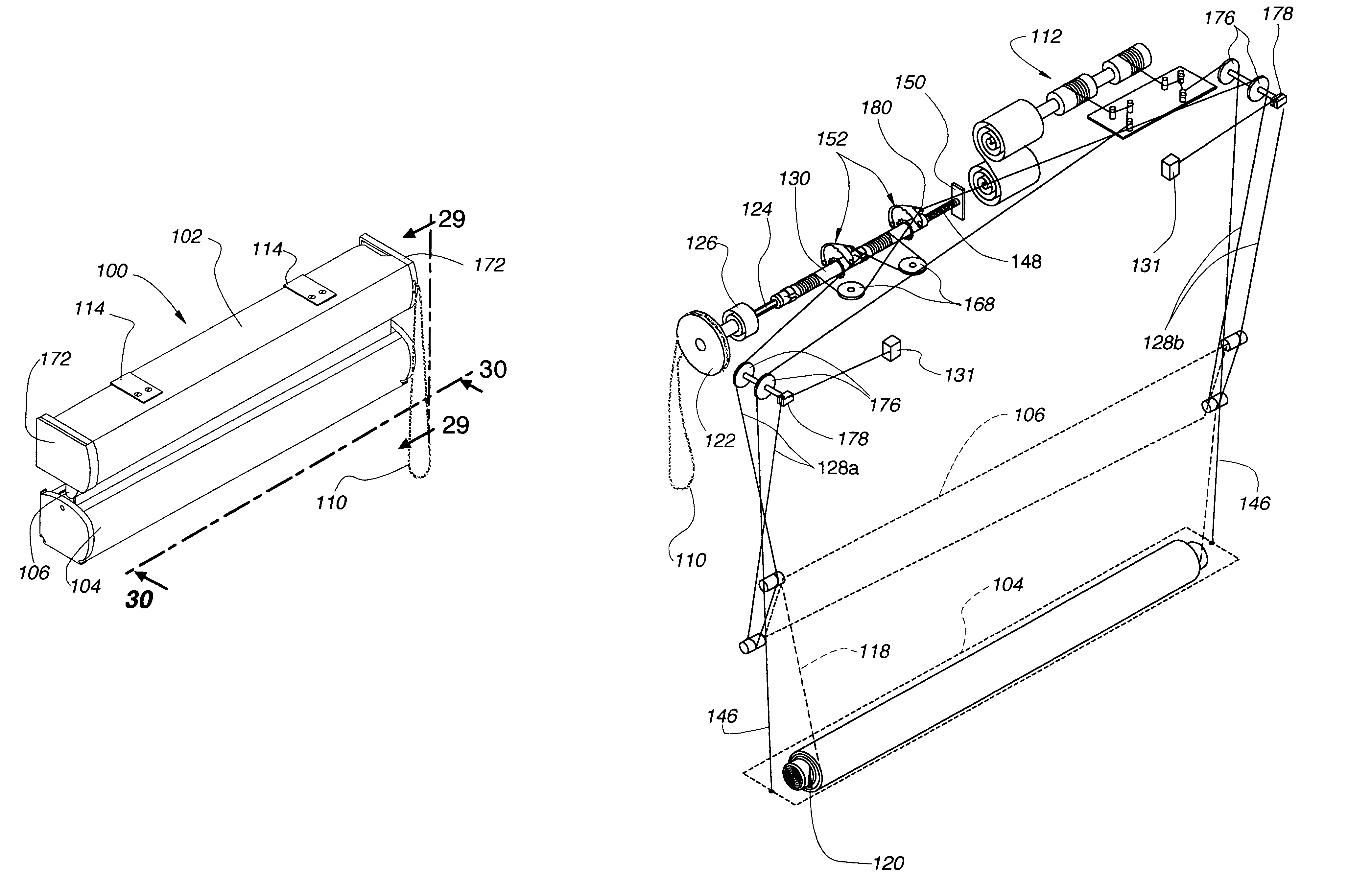
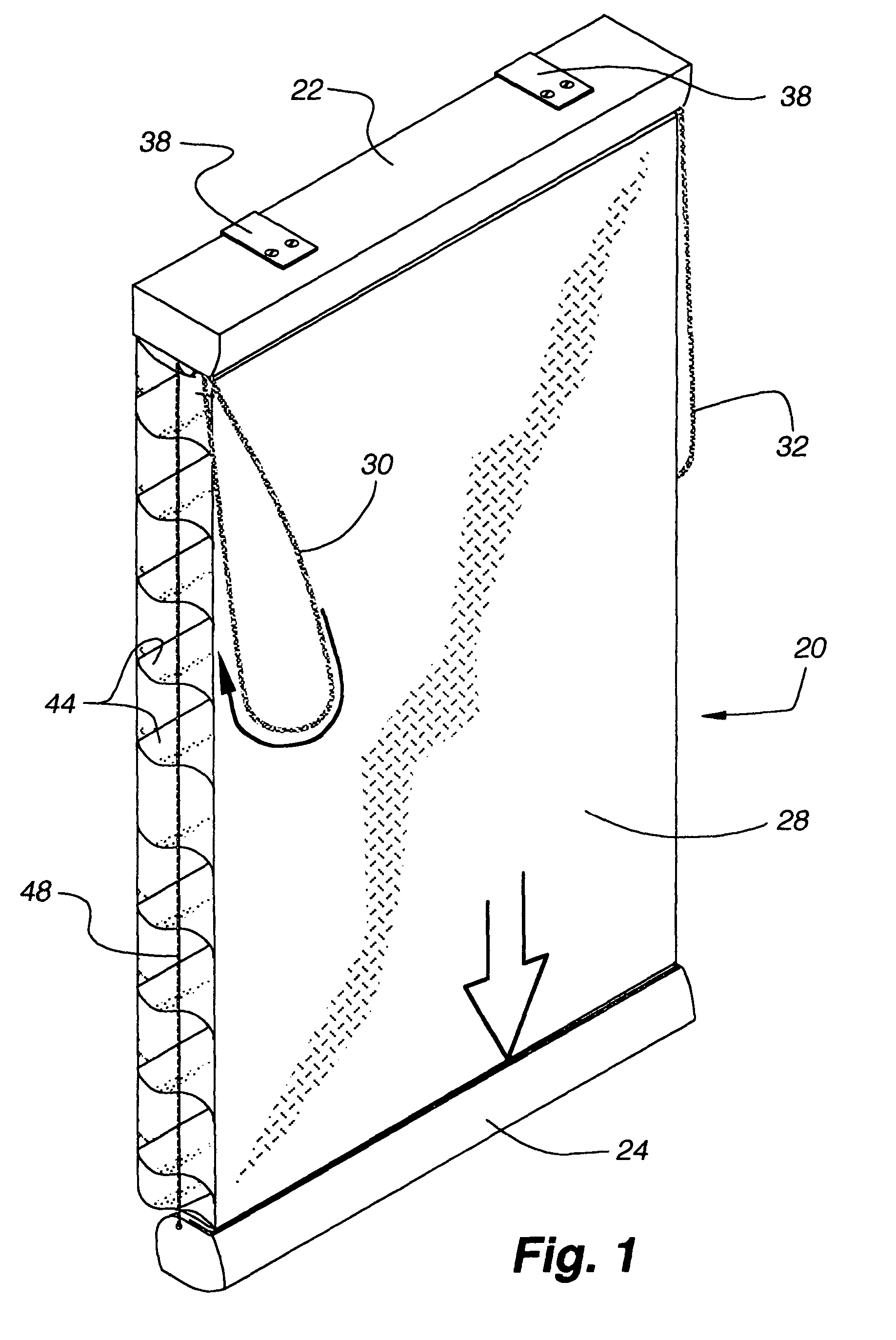
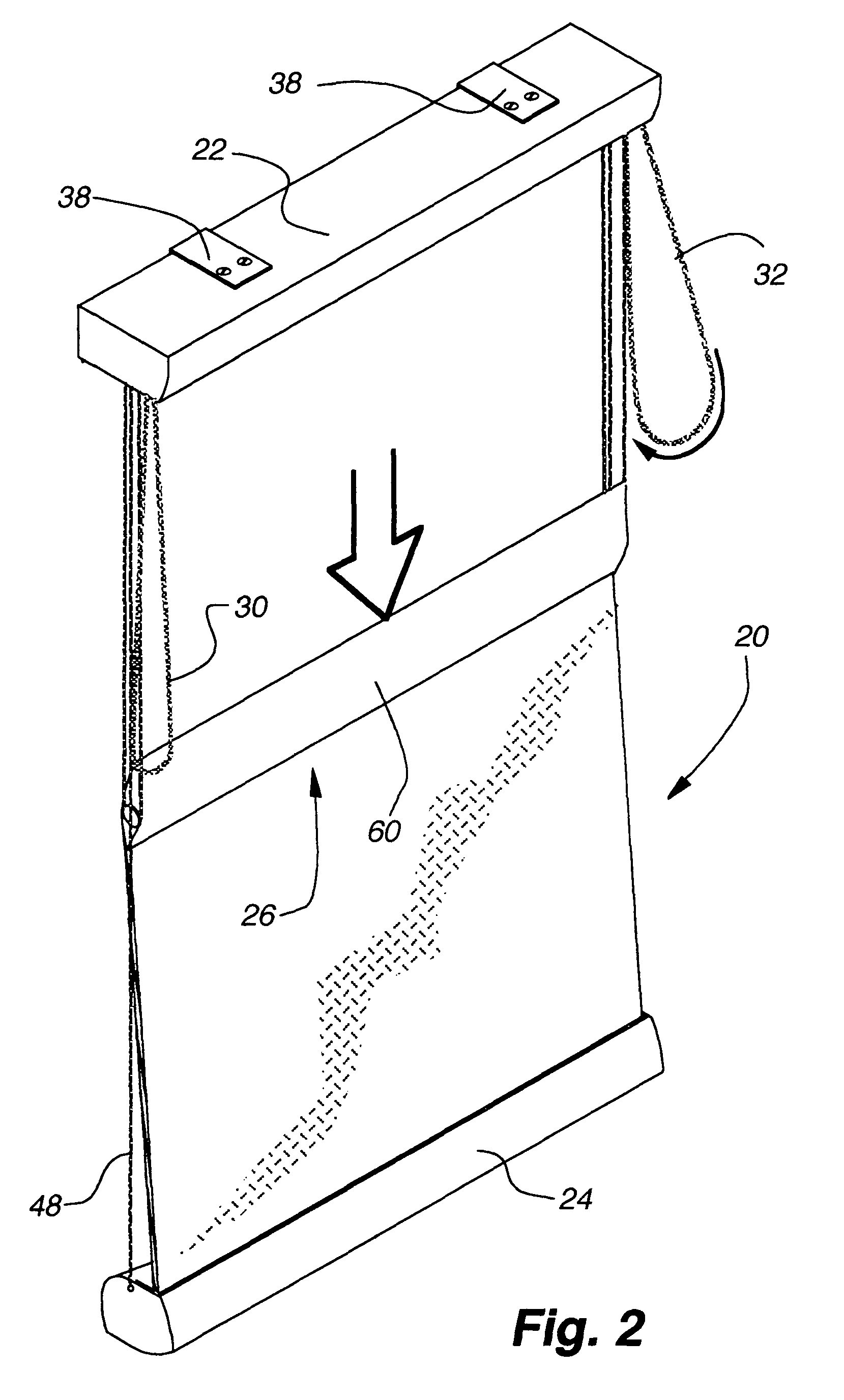
[0113]A first embodiment of a covering 20 in accordance with the present invention is shown in FIGS. 1 through 20 and with reference to FIG. 1 can be seen to include a head rail 22, a bottom rail 24, an intermediate rail 26, a flexible fabric material or structure 28 extending between the intermediate rail and the bottom rail and operating cords 30 and 32 for operating first 34 and second 36 control systems, respectively (FIGS. 9–12) for the covering. The first control system 34 enables movement of the bottom rail vertically between a fully retracted condition of the covering as shown, for example, in FIG. 12, and a fully extended condition as shown in FIG. 1. The second control system 36 is utilized to not only tilt the intermediate rail for purposes to be described later, but to also move the intermediate rail vertically between the fully retracted position of FIG. 1 and a fully extended position (not shown) wherein the intermediate rail is positioned adjacent to the bottom rail w...


PUM


Abstract

A covering for an architectural opening includes a head rail, a bottom rail with a take-up roller therein and an intermediate rail with both the intermediate rail and bottom rail suspended from the head rail, a fabric material interconnecting the intermediate rail with the bottom rail and being adapted to be wrapped around the roller in the bottom rail, said fabric including a pair of vertically oriented sheets that are horizontally spaced by a plurality of vertically spaced horizontal vanes with the vanes being movable between open and closed positions by opposite vertical movement of the sheets of material. In a first embodiment a first control system is provided for raising and lowering the bottom rail and a second control system for raising and lowering the intermediate rail as well as tilting the intermediate rail to effect an opening or closing of the vanes. In alternative embodiment, the bottom rail is controlled with a spring balanced system so that it remains in any position in which it is normally set.

Description

CROSS REFERENCE TO RELATED APPLICATIONS[0001]This application is a continuation-in-part of U.S. application Ser. No. 10 / 393,698, filed 18 Mar. 2003 now U.S. Pat. No. 6,834,701, which application claims the benefit of U.S. provisional application No. 60 / 366,286, filed 20 Mar. 2002. Each of the above-identified applications is hereby incorporated by reference as if fully disclosed herein.BACKGROUND OF THE INVENTION[0002]1. Field of the Invention[0003]This invention relates generally to retractable coverings for architectural openings or the like that include a pair of vertically oriented sheets horizontally spaced by a plurality of vertically spaced horizontally extending vanes. Oppositely directed vertical movement of the sheets causes the vanes to pivot about horizontal longitudinal axes between open and closed positions. In the open position, the vanes are horizontally disposed defining a gap therebetween permitting the passage of vision and light, and in a closed position, the van...

Claims


Application Information

Patent Timeline
IPC IPC(8): E06B9/08E06B9/262E06B9/264E06B9/64
CPCE06B9/262E06B9/264E06B9/64E06B2009/2627E06B2009/2435E06B9/34
Inventor COLSON, WENDELL B.GOLDBERG, MICHAEL S.DREW, TERRENCE M.JOSEPHSON, PAUL F.JELIC, RALPH G.
Owner HUNTER DOUGLAS INC
Why Eureka
Try Eureka