Self leveling towed implement

a technology of towed implements and tongues, which is applied in the direction of adjusting devices, agricultural tools and machines, constructions, etc., can solve the problems of not solving the problem in the fore-and-aft direction, the front or rear rank of tools is too deep into the soil, and the inability to properly engage the contours of the ground becomes more difficul

Inactive Publication Date: 2006-06-20
BLUE LEAF I P INC
View PDF15 Cites 96 Cited by
  • Summary
  • Abstract
  • Description
  • Claims
  • Application Information

AI Technical Summary

Benefits of technology

[0006]In accordance with the first embodiment of the invention, a system for leveling an implement having a tongue engageable to a towing vehicle for towing the implement is provided including a hydraulic cylinder having a first hydraulic fluid port disposed to move the cylinder when filled with fluid in a first direction wherein the cylinder is mechanically culpable to the tongue to raise and lower the tongue with respect to the implement when the cylinder is actuated, a first gas-filled hydraulic accumulator fluidly coupled to the first hydraulic fluid port on the cylinder, a first on / off valve coupled between the first accumulator and the first hydraulic fluid port on the cylinder to connect and disconnect the first accumulator from fluid communication with the cylinder, and a first directional control valve to selectively connect the first hydraulic both to a source of hydraulic fluid under pressure to fill the cylinder with hydraulic fluid and to a hydraulic tank to drain the cylinder of hydraulic fluid. The system may include an operator-actuable switch for actuating the first on / off valve. The system may include a first check valve disposed between the first hydraulic fluid port and the first directional control valve and disposed to limit the return of fluid from the first hydraulic fluid port to the first directional control valve. The cylinder may have a second hydraulic fluid port disposed to move the cylinder when filled with fluid in a second direction opposite the first direction and the system may include a second gas-filled hydraulic accumulator fluidly coupled to the second hydraulic fluid port on the cylinder, a second on / off valve coupled between the second accumulator and the second hydraulic fluid port on the cylinder to connect and disconnect the second accumulator from fluid communication with the cylinder, and a second directional control valve to selectively connect the second hydraulic port both to the source of hydraulic fluid under pressure to fill the cylinder with hydraulic fluid and to the hydraulic tank to drain the cylinder of hydraulic fluid. The first and second directional control valves may be coupled to drain fluid from the cylinder through the first hydraulic fluid port to the tank while simultaneously filling the cylinder with hydraulic fluid through the second hydraulic fluid port from the hydraulic supply. The operator-actuable switch may also actuate the second on / off valve. A second check valve may be disposed between the second hydraulic fluid port and the second directional control valve and be disposed to limit the return of fluid from the second hydraulic fluid port to the second directional control valve. The first and second check valves may be pilot operated, wherein a pilot line for each of the first and second check valves is cross-coupled to the other of the first and second check valves.

Problems solved by technology

A major problem in designing these implements is in providing them with sufficient flexibility to accurately follow the contours of the ground in the agricultural fields in which they are used.
The ability to properly engage the contours of the ground becomes more difficult as the lateral dimensions of the implements increase.
While dividing an implement up into laterally hinged sections solves the contour-following problem in a side-to-side direction, it does not solve the problem in a fore-and-aft direction.
If the implement's tongue itself is tilted too high or too low, it can cause the front or rear rank of tools to dig too deeply into the soil even when the tractor and implement are traveling over smooth and level ground.
One problem with this spring loaded tongue adjustment system, however, is particularly troublesome with larger implements having longer laterally extending wings when traveling over the road.
For implements supported on two or more wheels spaced laterally along a single side-to-side line, however, this arrangement is unstable and permits fore-and-aft oscillation of the wings as the spring loaded tongue flexes up and down.

Method used


Image

  • Self leveling towed implement
  • Self leveling towed implement
  • Self leveling towed implement

Examples


Embodiment Construction

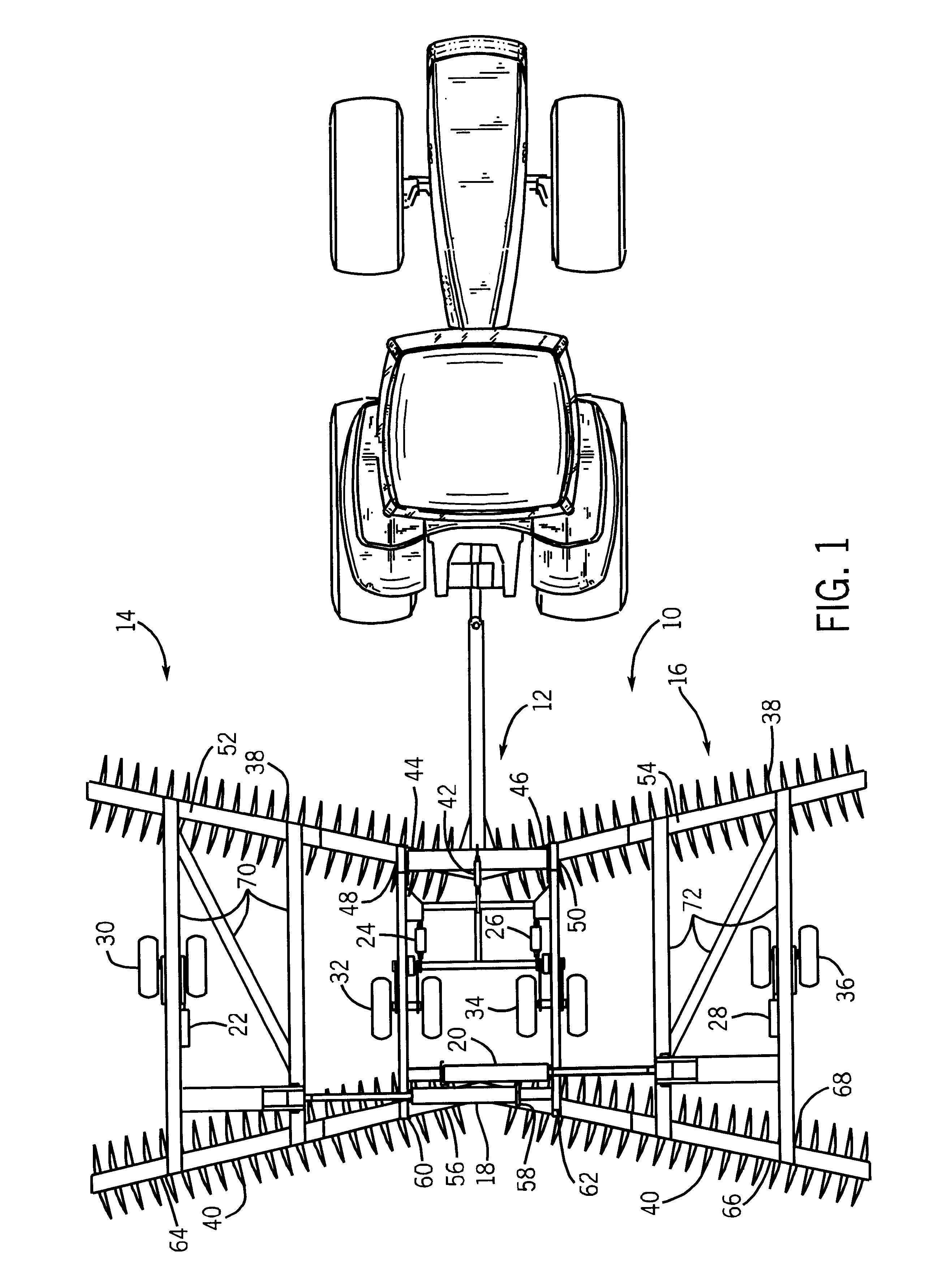
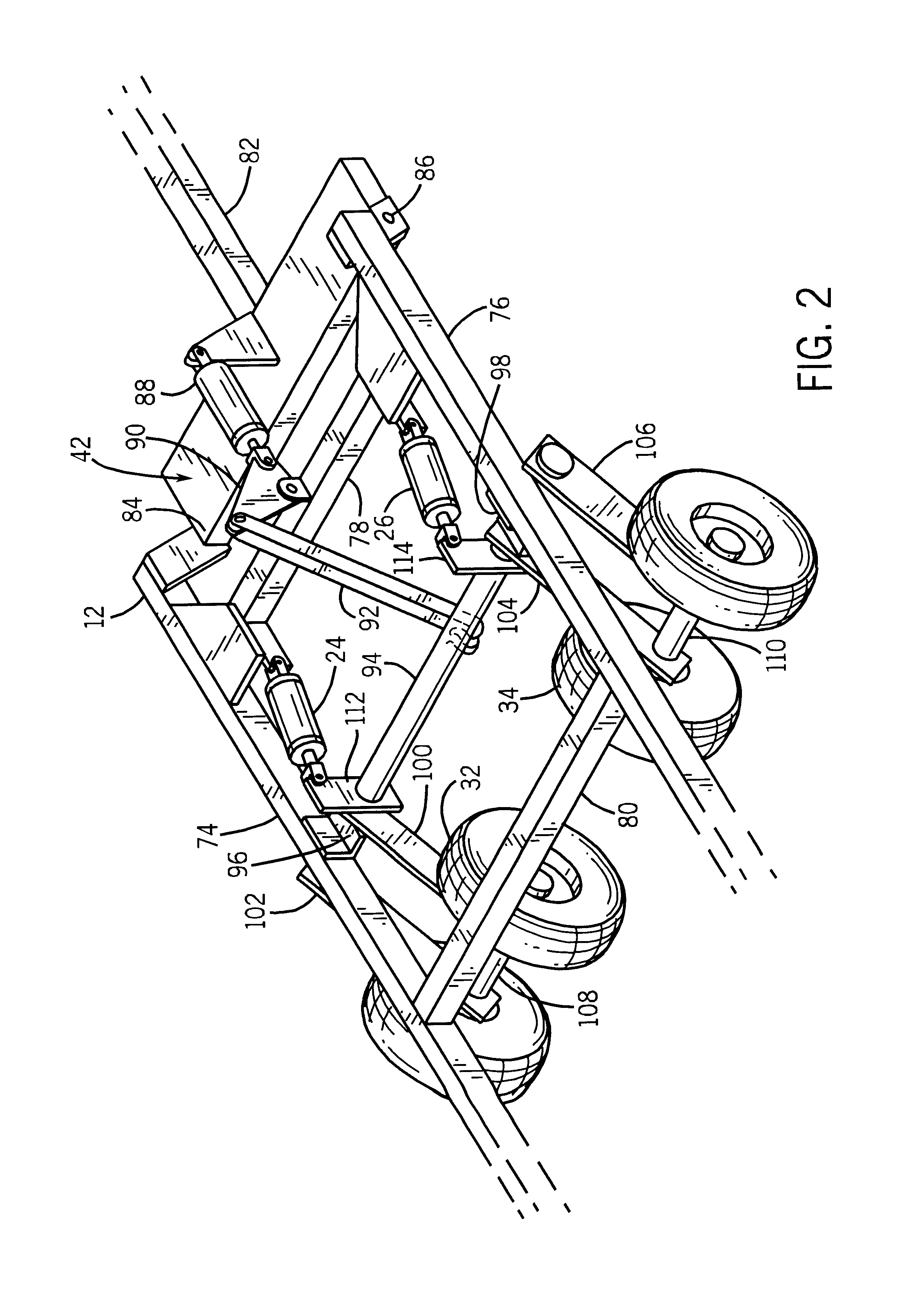
[0016]In FIG. 1, an implement 10 is illustrated having a central frame 12, two wings 14 and 16 pivotally coupled to the central frame, lift actuators 18 and 20 for lifting the wings above the frame, wheel actuators 22, 24, 26, and 28 for raising and lowering wheel sets 30, 32, 34, and 36, front tool gang 38 fixed to the front of the frame and wings, rear tool gang 40 fixed to the rear of the frame and wings, and leveling mechanism 42 for leveling the implement.

[0017]Front tool gang 38 includes inner forward gang tubes 44 and 46 which are bolted to central frame 12 and extend laterally away from the central frame. These gang tubes have pivotal couplings 48 and 50 disposed at their outer ends to which outer forward gang tubes 52, 54, respectively, are pivotally connected.

[0018]Rear tool gang 40 includes inner rear gang tubes 56 and 58 which are bolted to central frame 12 and extend laterally away from the central frame. These gang tubes have pivotal couplings 60 and 62 disposed at the...


PUM


Abstract

An implement has a tongue used to tow the implement that can be raised or lowered with respect to the rest of the implement. The tongue is raised or lowered by a hydraulic cylinder. The raising and lowering ports of the cylinder are connected to two hydraulic accumulators to permit the tongue to flex up or down while the implement is towed through the field. These accumulators are disconnected from the cylinder when the wings of the implement are lifted and the implement is towed over the road to prevent the implement from oscillating backwards and forward about an axis defined by its wheels.

Description

FIELD OF THE INVENTION[0001]The invention relates generally to towed agricultural implements. More particularly it relates to implements having an adjustable tongue.BACKGROUND OF THE INVENTION[0002]Many agricultural implements are designed to be towed behind a towing vehicle such as a tractor. A major problem in designing these implements is in providing them with sufficient flexibility to accurately follow the contours of the ground in the agricultural fields in which they are used. It is essential that many ground engaging implements such as harrows, rakes, seeders, planters, and chemical applicators, follow the ground contours accurately. All of these implements are designed to engage and process the soil at quite specific depths on the order of a few inches. The ability to properly engage the contours of the ground becomes more difficult as the lateral dimensions of the implements increase. A partial solution is provided by dividing the implement up into a plurality of sections,...

Claims


Application Information

Patent Timeline
Patent Type & Authority Patents(United States)
IPC IPC(8): A01B49/00A01B63/00
CPCA01B73/044A01B63/22
Inventor STASZAK, ALBERT W.SANDERSON, DONALD J.BIRKENBACH, EUGEN J.
Owner BLUE LEAF I P INC
Why Eureka
Try Eureka