Device for fixing a power circuit breaker in an insertion rack

a technology for fixing devices and power circuit breakers, which is applied in the direction of air break switches, high-tension/heavy-dress switches, electrical apparatuses, etc., can solve the problems of hidden risk of locking being forgotten, circuit breakers out, failure or destruction of devices, etc., and achieves simple and secure effects

Inactive Publication Date: 2006-06-20
SIEMENS AG
View PDF10 Cites 30 Cited by
  • Summary
  • Abstract
  • Description
  • Claims
  • Application Information

AI Technical Summary

Benefits of technology

[0012]The apparatus according to an embodiment of the invention for fixing a power circuit breaker in a withdrawable-part rack advantageously makes it possible for the power circuit breaker to be locked in a simple and secure manner. As a result of the fact that this apparatus interacts with a device for moving the power circuit breaker relative to the withdrawable-part rack, it is particularly advantageous to fix the power circuit breaker as a result of the movement of the power circuit breaker into the withdrawable-part rack and also to unlatch the power circuit breaker owing to the withdrawal of the power circuit breaker from the withdrawable-part rack. Thus, no additional procedures by an operator are required for fixing the power circuit breaker.

Problems solved by technology

As a result of the arrangement of the current path in the power circuit breaker, forces result which would produce a torque about the insertion shaft and would thus push the power circuit breaker out of the withdrawable-part rack if insufficient fixing were provided.
The formation of an arc associated with this may result in failure or destruction of the device.
If a strong force is introduced, the power circuit breaker accordingly tends towards tipping movements, with the result that the mentioned disadvantages occur.
Analogous locking for a withdrawable-part rack equipped with a device for inserting the power circuit breaker does not, however, have to be undertaken by hand, which would then have the hidden risk of locking being forgotten.

Method used


Image

  • Device for fixing a power circuit breaker in an insertion rack
  • Device for fixing a power circuit breaker in an insertion rack
  • Device for fixing a power circuit breaker in an insertion rack

Examples


Embodiment Construction

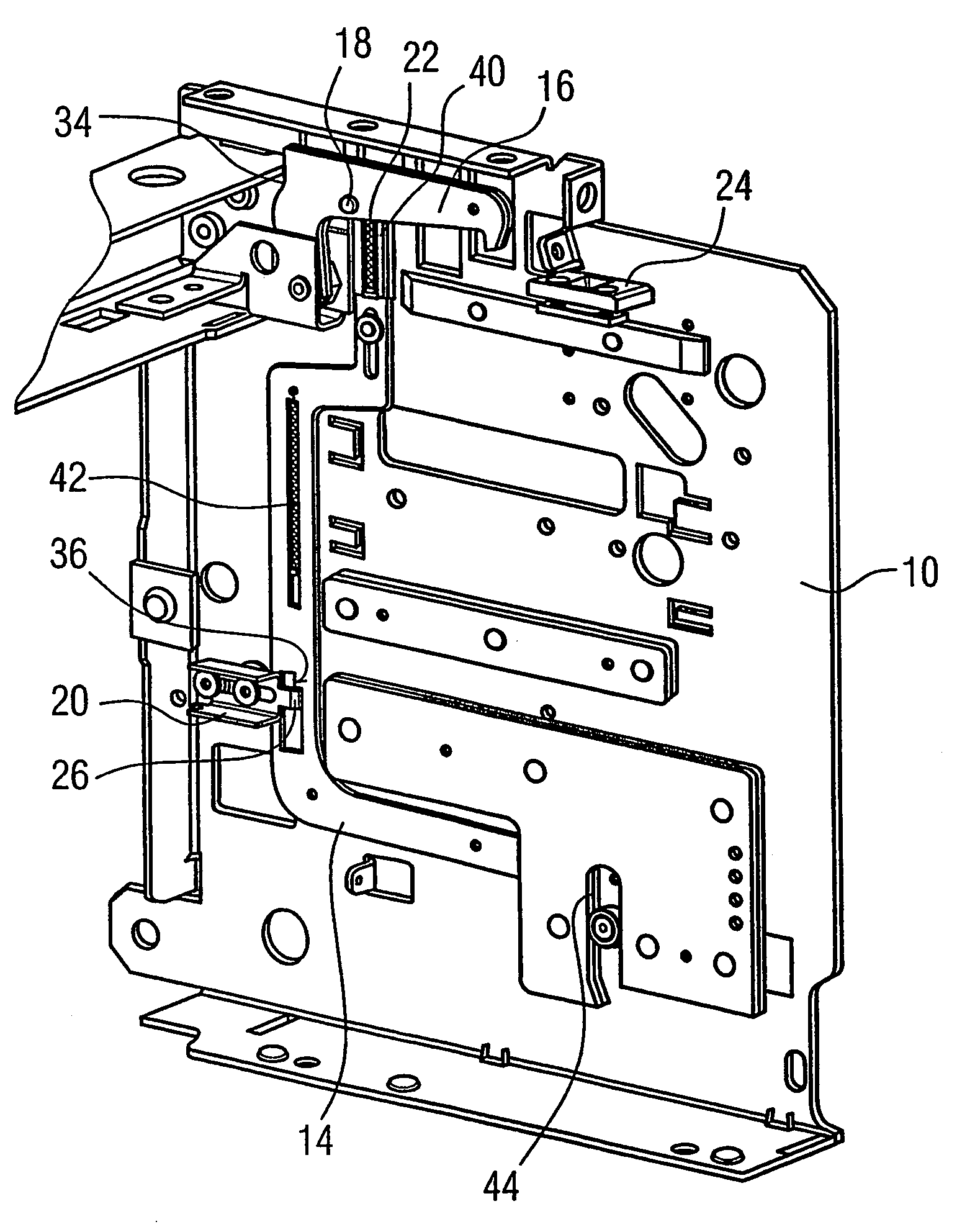
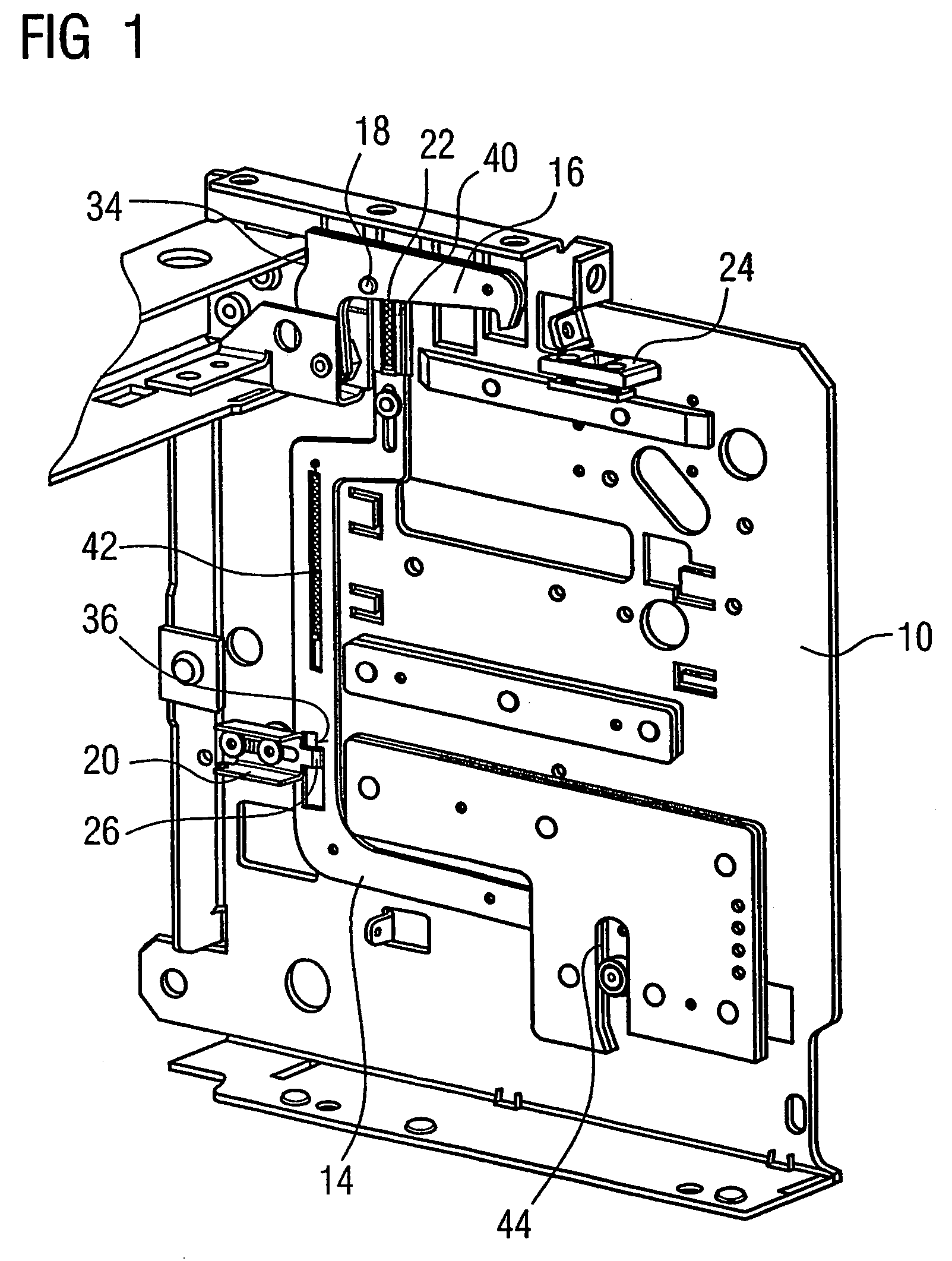
[0026]FIG. 1 shows a perspective illustration of an apparatus according to an embodiment of the invention, which is arranged on a withdrawable-part rack 10, a power circuit breaker 12 being partially inserted in the withdrawable-part rack 10. For greater clarity, only one attachment 24 of the power circuit breaker 12 is illustrated. The apparatus for fixing the power circuit breaker 12 in the withdrawable-part rack 10 is fixed on the side wall of the withdrawable-part rack 10 and engages, in the latched position, in the attachment 24 of the power circuit breaker 12.

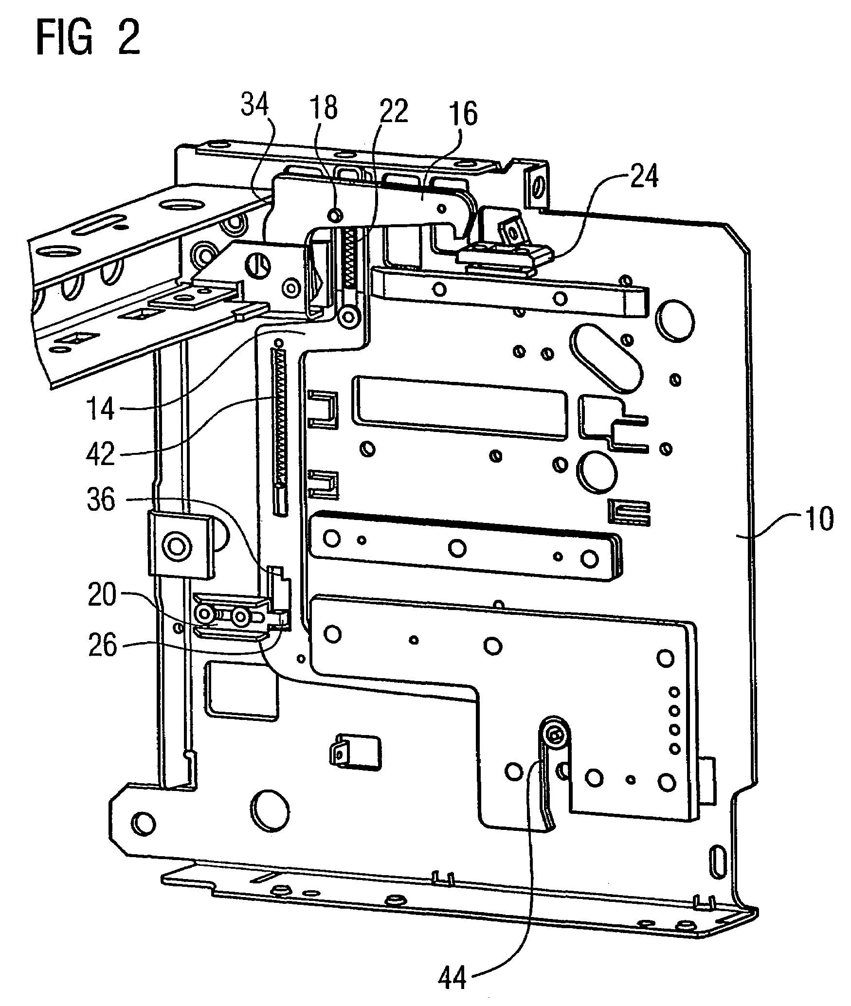
[0027]In the initial position, the control rod 14 is locked in a blocked position by a transverse slide 20. The result is that a locking device 16 is located in an unlatched position. The power circuit breaker 12 is moved into the withdrawable-part rack 10 by way of a displacement mechanism, which has a crank handle 29 and an insertion shaft 30 having a crankshaft journal 32.

[0028]A locking device 16 is located at this po...


PUM


Abstract

A device is for fixing a circuit breaker in an insertion rack. The device includes at least one arresting unit which is connected to the insertion rack and belongs to the power circuit breaker. The arresting unit is connected to a control rod which is movably arranged on the insertion rack in such a way that it is displaceable from a locking position to an unlocking position and vice-versa. The control rod interacts with a system which moves the power circuit breaker in relation to the insertion rack. The device also includes a release device which can be displaced from the locking position of the control rod to the releasing position thereof and vice-versa by way of the power circuit breaker.

Description

[0001]This application is the national phase under 35 U.S.C. § 371 of PCT International Application No. PCT / DE2003 / 002884 which has an International filing date of 28 Aug. 2003 (28.08.2003), which designated the United States of America and which claims priority on German Patent Application number DE 102 50 214.5 filed 24 Oct. 2002 (24.10.2002), the entire contents of which are hereby incorporated herein by reference.FIELD OF THE INVENTION[0002]The invention generally relates to an apparatus for fixing a power circuit breaker in a withdrawable-part or insertion rack. It more specifically may relate to one having a device for moving the power circuit breaker relative to the withdrawable-part or insertion rack and at least one locking device, associated with the withdrawable-part rack, for the power circuit breaker. The locking device may be connected to a control rod, arranged movably on the withdrawable-part rack, for the purpose of moving it from a latched position to an unlatched ...

Claims


Application Information

Patent Timeline
Patent Type & Authority Patents(United States)
IPC IPC(8): H01H9/00H02B11/133
CPCH02B11/133
Inventor DEYLITZ, ERHARDKRUSCHKE, MICHAELMAREK, KATHRINA
Owner SIEMENS AG
Why Eureka
Try Eureka