Electrochromic devices having no positional offset between substrates

Inactive Publication Date: 2006-06-20
GENTEX CORP
View PDF17 Cites 243 Cited by
  • Summary
  • Abstract
  • Description
  • Claims
  • Application Information

AI Technical Summary

Problems solved by technology

While the above-described structure is readily manufacturable, styling concerns have arisen with respect to the width of the front lip of the bezel of an electrochromic mirror subassembly.

Method used


Image

  • Electrochromic devices having no positional offset between substrates
  • Electrochromic devices having no positional offset between substrates
  • Electrochromic devices having no positional offset between substrates

Examples


Embodiment Construction

[0060]Reference will now be made in detail to the present preferred embodiments of the invention, examples of which are illustrated in the accompanying drawings. Wherever possible, the same reference numerals will be used throughout the drawings to refer to the same or like parts. In the drawings, the depicted structural elements are not to scale and certain components are enlarged relative to the other components for purposes of emphasis and understanding.

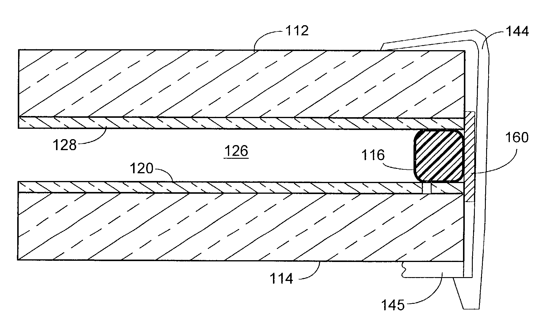
[0061]As described above, the electrochromic mirror subassemblies provide the advantage of a reduced bezel front lip width of preferably about 4 mm or less, and more preferably about 3.6 mm, while still extending over all of the seal width, and preferably extending about 0.5 mm beyond an innermost edge of the seal so as to sufficiently obscure the view of the seal. According to some aspects of the present invention, a bezel may not even be utilized due to other inventive techniques for obscuring the view of the seal through the fi...


PUM

PropertyMeasurementUnit
widthaaaaaaaaaa
width D1aaaaaaaaaa
widthaaaaaaaaaa

Abstract

To allow an electrochromic device to have little or no offset between its front and rear elements, an electrical conductor may be provided to electrically couple a portion of a first conductive layer provided on the rear surface of the front element with a portion of a second conductive layer provided on the front surface of the rear element. The electrical conductor may be in the form of a conductive portion of the seal. To prevent shorting across the electrochromic medium, at least one of the first and second conductive layers is separated into a first portion and a second portion that is electrically isolated from the first portion and is in electrical contact with the electrochromic material. An elastomeric bezel may be utilized. Also, an edge seal may optionally be employed so as to reduce the need or width of the bezel.

Description

BACKGROUND OF THE INVENTION[0001]The present invention generally relates to electro-optic devices, and more particularly relates to electrochromic devices used in architectural windows or vehicle rearview mirrors.[0002]Electrochromic elements are used in a variety of applications including light shutters, variable attenuating optical filters, and architectural and vehicle windows. The most common application of electrochromic elements is in rearview mirror assemblies used in vehicles. Such electrochromic rearview mirrors are controlled to vary the reflectivity of the mirror in response to rearward and forward aimed light sensors so as to reduce the glare of headlamps in the image reflected to the driver's eyes.[0003]FIG. 1A shows an exploded view of a portion of a rearview mirror subassembly 5 as used in a typical exterior rearview mirror assembly. Subassembly 5 includes an electrochromic mirror element 10, a bezel 50, and a carrier plate 70 (FIG. 1B). The subassembly may further in...

Claims


Application Information

Patent Timeline
Patent Type & Authority Patents(United States)
IPC IPC(8): G02F1/15G02F1/153B60R1/08G02F1/161G02F1/163
CPCB32B17/06B32B17/10036B32B17/10174B32B17/10321G02F1/163B60R1/088G02F1/1533G02F1/161B32B17/10513
Inventor TONAR, WILLIAM L.CAMMENGA, DAVID J.POLL, DAVID L.KAR, KEVIN B.BUSSCHER, BRADLEY L.
Owner GENTEX CORP
Why Eureka
Try Eureka