Hardness tester

a test device and hardness technology, applied in the direction of material hardness investigation, material strength using repeated/pulse forces, instruments, etc., can solve the problems of inaccurate test results, and inability to test the hardness of irregular material

Active Publication Date: 2006-06-27
WUSOMING
View PDF8 Cites 5 Cited by
  • Summary
  • Abstract
  • Description
  • Claims
  • Application Information

AI Technical Summary

Benefits of technology

[0008]A main object of the present invention is to provide a hardness tester, which allows the user to precisely measure the hardness of the material having a limited testing surface thereof.
[0009]Another object of the present invention is to provide a hardness tester, which comprises a driving axle coaxially aligned with a penetrating pin, and a transmission shaft physically contacted between the driving axle and the penetrating pin for transmitting the penetrating force from the driving axle to the penetrating pin so as to minimize the error of the test result through the testing operation due to the unwanted lateral movement of the driving axle.
[0010]Another object of the present invention is to provide a hardness tester, wherein no supporting surface of the testing material is required during the testing operation of the hardness tester of the present invention so as to minimize the error of the test result through the testing operation due to the irregular shape of the testing material.

Problems solved by technology

However, such conventional hardness meter has several drawbacks.
Therefore, the testing material having an irregular shaped cannot be tested by such convention hardness meter.
Otherwise, the test result of the hardness of the testing material will not accurate due to the uneven testing surface or the uneven supporting surface of the testing material.
Therefore, the test result may not precise due to the mechanical deviation of the force sensor.
However, it is known that the compression spring will be deteriorated after a period of time.
In other words, both conventional measurement devices of the hardness meter cannot precisely determine the hardness of the testing material due to the mechanical deviation.

Method used


Image

  • Hardness tester
  • Hardness tester
  • Hardness tester

Examples


Embodiment Construction

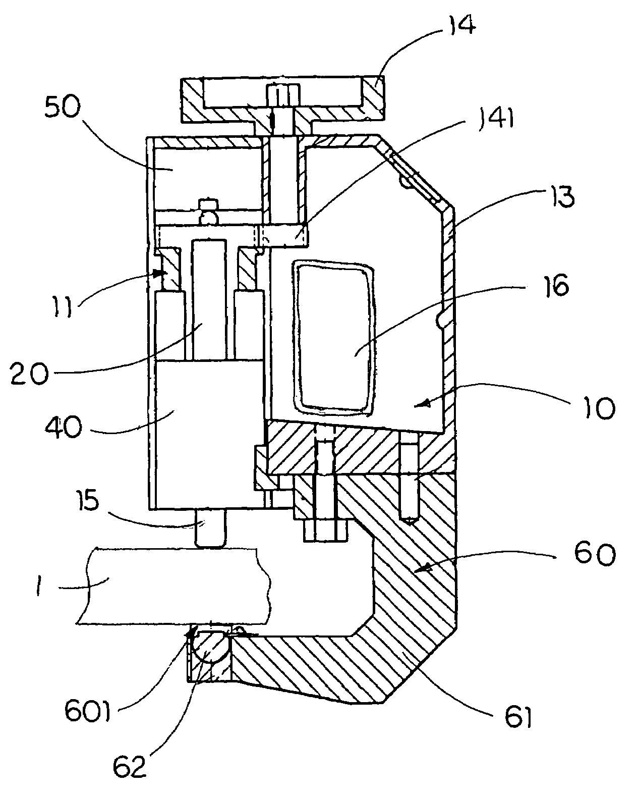
[0026]Referring to FIGS. 1 and 2 of the drawings, a hardness tester according to a preferred embodiment of the present invention is illustrated, wherein the hardness tester is adapted for measuring a hardness of a tested object 1 having a testing surface.

[0027]The hardness tester comprises a supporting frame 10 having a receiving chamber 11 and an elongated guiding channel 12 coaxially extended to communicate with the receiving chamber 11, a driving axle 20 slidably disposed in the receiving chamber 11 of the supporting frame 10, and a penetrating pin 30 coaxially disposed in the guiding channel 12 in a slidably movable manner to coaxially align with the driving axle 20 for the pin head 31 to penetrate on the testing surface of the tested object 1.

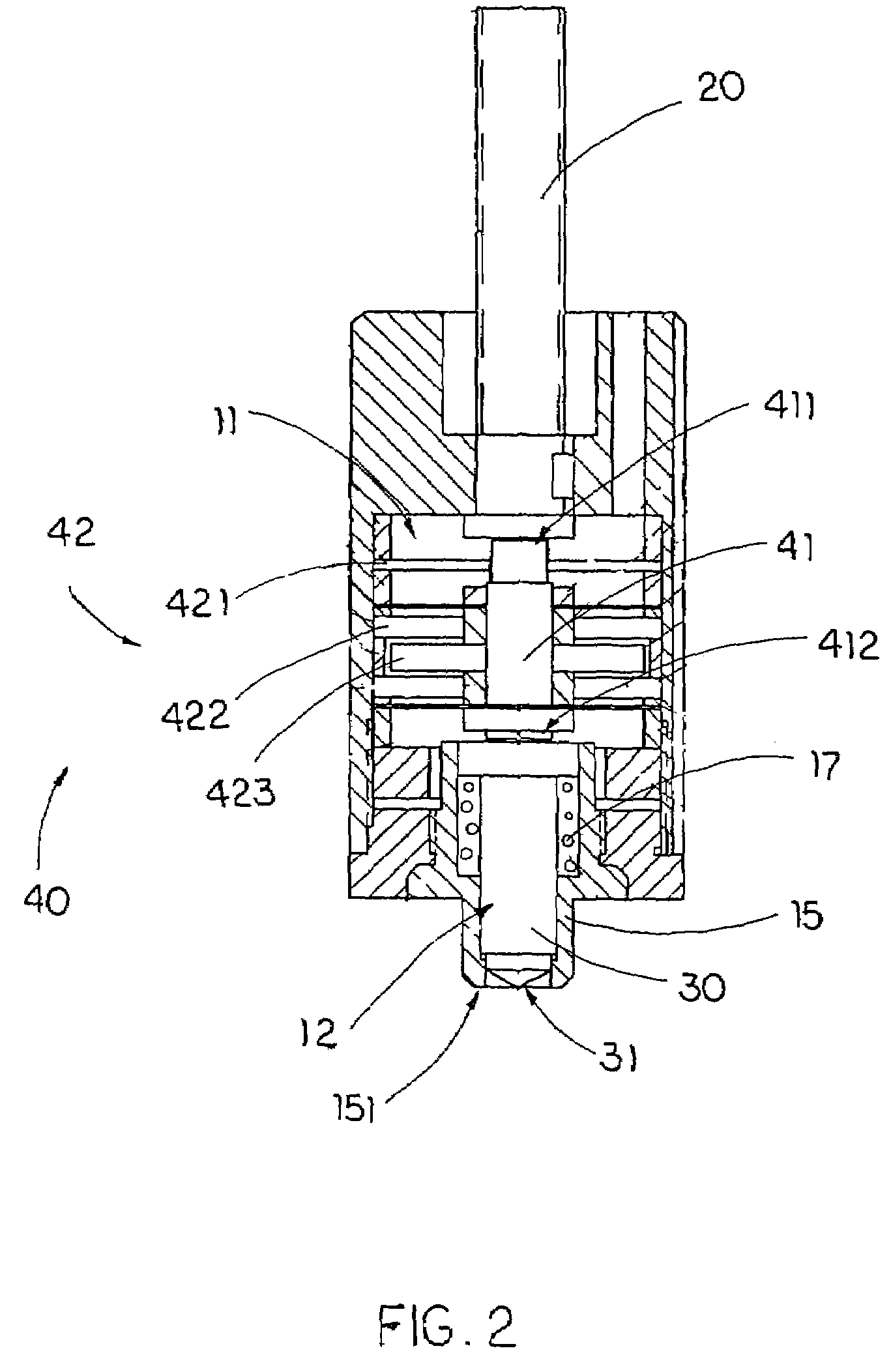
[0028]The hardness tester further comprises a linear displacement device 40 which comprises a transmission shaft 41 movably disposed in the receiving chamber 11 at a position universally contacting between the driving axle 20 and the penet...


PUM

PropertyMeasurementUnit
hardness testeraaaaaaaaaa
hardnessaaaaaaaaaa
penetrating forceaaaaaaaaaa

Abstract

A hardness tester includes a supporting frame having a guiding channel, a driving axle slidably disposed in the supporting frame, and a penetrating pin, having a pin head, coaxially disposed in the guiding channel in a slidably movable manner to coaxially align with the driving axle for the pin head to penetrate on a testing surface of a tested object. A linear displacement device includes a transmission shaft movably disposed in the supporting frame at a position universally contacting between the driving axle and the penetrating pin, and a displacement sensor supported at the transmission shaft, wherein when the driving axle is driven for applying a penetrating force to the penetrating pin through the transmission shaft, the linear sensor detects a linear displacement of the transmission shaft with respect to the penetrating pin for measuring the hardness of the tested object.

Description

BACKGROUND OF THE PRESENT INVENTION[0001]1. Field of Invention[0002]The present invention relates to a material hardness measuring device, and more particularly to a hardness tester, which allows the user to precisely measure the hardness of the material having a limited testing surface thereof.[0003]2. Description of Related Arts[0004]Hand-operated portable hardness meters are already known wherein a conventional hardness meter generally comprises a supporting frame having a flat supporting platform and an actuating gun comprising a driving pin slidably to align with the supporting platform in such a manner that when the testing material is positioned between the supporting platform and the driving pin, a penetrating force of the driving pin is exerted on the testing material so as to determine the hardness of the testing material through the penetrating force. Accordingly, the penetrating force includes a major loading force and a minor loading force wherein the result of the hard...

Claims


Application Information

Patent Timeline
Patent Type & Authority Patents(United States)
IPC IPC(8): G01N3/34G01N3/42
CPCG01N3/42
Inventor WU, SHAOMING
Owner WUSOMING
Why Eureka
Try Eureka