LED lighting system

a technology of led lighting and led diodes, which is applied in the direction of electric variable regulation, process and machine control, instruments, etc., can solve the problems of drifting led color, complex and expensive logistics of managing so many bins, and unsatisfactory led manufacturing process

Inactive Publication Date: 2006-06-27
LUMINATOR HLDG
View PDF4 Cites 117 Cited by
  • Summary
  • Abstract
  • Description
  • Claims
  • Application Information

AI Technical Summary

Problems solved by technology

In reality, the LED manufacturing process is not perfect, and manufacturers have to bin (sort) the LEDs by intensity and wavelength.
The logistics of managing so many bins is both complex and expensive.
Unfortunately, the intensity level of an LED changes with temperature, which can cause a drift in the LED's color.
Since the resultant color generated by the lighting system is composed of three or more colors, a minor shift in output of any one of the component colors may lead to visible color shifts.

Method used


Image

  • LED lighting system
  • LED lighting system
  • LED lighting system

Examples


Embodiment Construction

[0025]Following is a detailed description of embodiments of the invention with reference to the drawings wherein numerals for similar elements are carried forward.

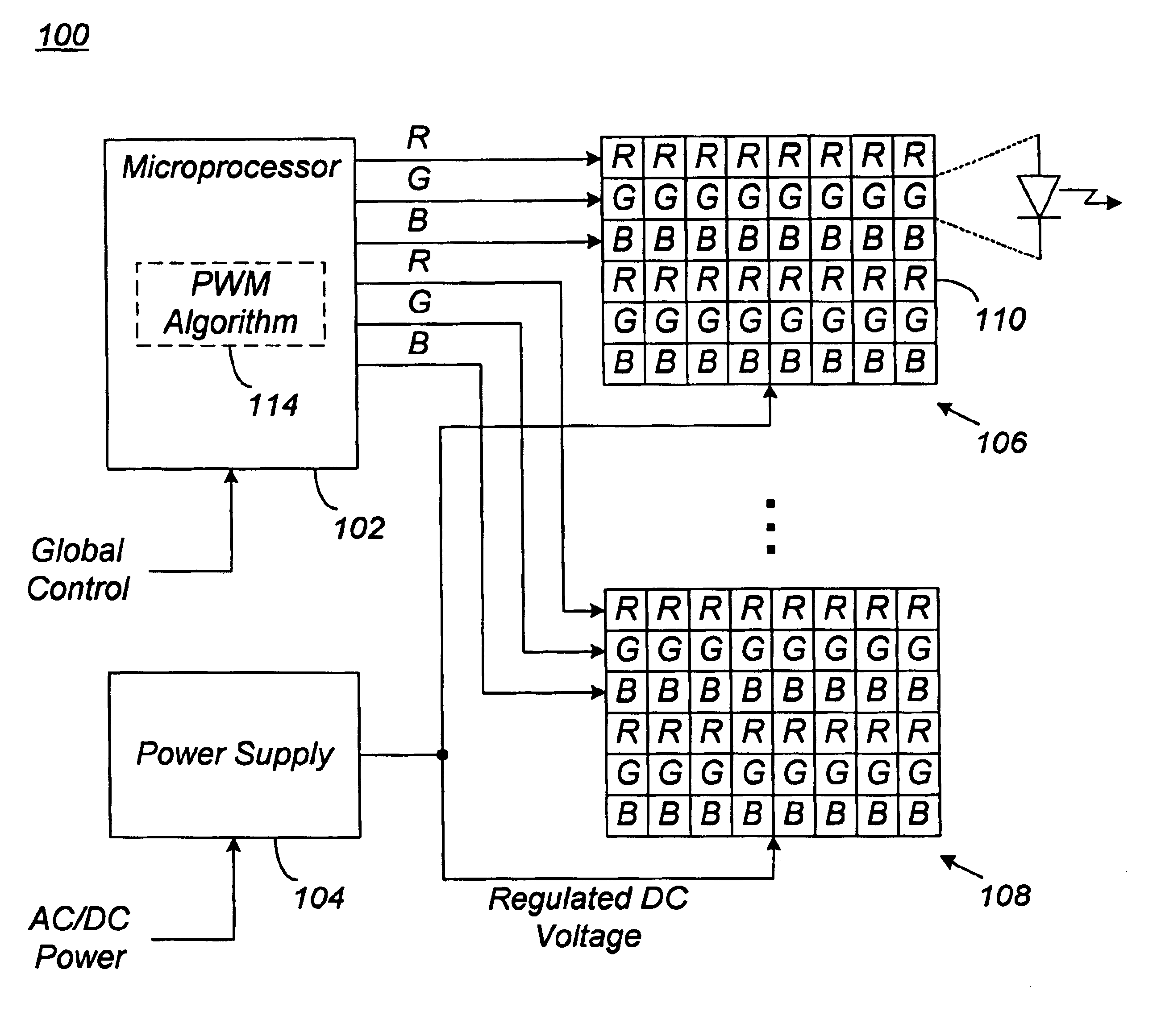
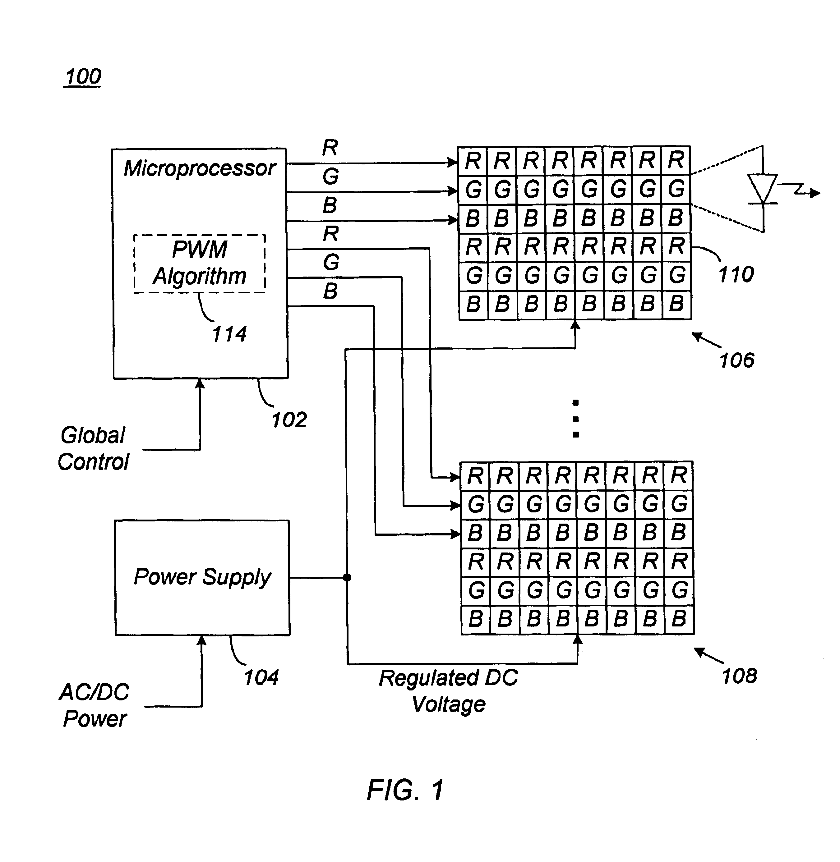
[0026]As mentioned previously, embodiments of the invention provide a method and system for compensating for color variations in an LED based lighting system due to changes in the operating temperature. The method and system of the invention involves calibrating the LEDs at a calibration temperature to produce a desired resultant color. The LEDs are then characterized at one or more different temperatures to determine a compensation curve. This compensation curve is then used to adjust the PWM of the LEDs to produce substantially the same desired resultant color under a different operating temperature.

[0027]The calibration temperature may be any suitable temperature, but is typically the temperature of the LED array after the LEDs have been powered on using some predefined PWM for some predefined calibration period (e.g., ...


PUM


Abstract

Method and system are disclosed for compensating for color variations due to thermal differences in LED based lighting systems. The method and system involves characterizing the LEDs to determine what PWM (pulse-width modulation) is needed at various operating temperatures to achieve a desired resultant color. The characterization data is then stored in the microprocessor either in the form of a correction factor or as actual data. When an operating temperature that is different from a calibration temperature is detected, the characterization data is used to adjust the PWM of the LEDs to restore the LEDs to the desired resultant color.

Description

CROSS REFERENCE TO RELATED APPLICATIONS[0001]This application is a continuation-in-part of U.S. Utility application Ser. No. 10 / 345,060, entitled “LED Lighting System,” filed on Jan. 15, 2003, which is hereby incorporated by reference.FIELD OF THE INVENTION[0002]The present invention is directed to light emitting diode (LED) based lighting systems and, in particular, to a method and system for compensating for color variation in the LED due to temperature differences.BACKGROUND OF THE INVENTION[0003]Lighting systems based on LEDs have an advantage over traditional fluorescent lighting systems in that they can be controlled to vary both their color and brightness. Through an appropriate combination of these two parameters, subtle lighting effects such as sunrise, sunset, and mood lighting can be achieved. Because of this and other advantages, LED based lighting systems are rapidly replacing traditional fluorescent lighting systems in a number of environments, including transportation...

Claims


Application Information

Patent Timeline
Patent Type & Authority Patents(United States)
IPC IPC(8): H05B37/00B60QH05B41/24H05B44/00
CPCH05B33/0803H05B33/0818H05B33/0821H05B33/0827H05B33/086H05B33/0869H05B33/0872H05B33/089H05B33/0863Y10S362/80Y02B20/346H05B45/20H05B45/22H05B45/40H05B45/46H05B45/325H05B45/56Y02B20/30
Inventor GUNTER, JOHN B.BERMAN, GEORGEBERGER, VALERIY K.
Owner LUMINATOR HLDG
Why Eureka
Try Eureka