Meta-element antenna and array

a meta-element antenna and array technology, applied in the direction of leaky waveguide antennas, antennas, electrically short antennas, etc., can solve the problems of many communication and sensing systems that are impractical today, lack of simple means of feeding the antenna with an arbitrary waveform or receiving a signal, and high cost and complexity

Active Publication Date: 2006-06-27
HRL LAB
View PDF189 Cites 417 Cited by
  • Summary
  • Abstract
  • Description
  • Claims
  • Application Information

AI Technical Summary

Problems solved by technology

Furthermore, there are many communication and sensing systems that are impractical today, but that would be enabled by the existence of a low-cost or lightweight phased array.
3), which are typically steered by pulling the phase of the edge elements, but often lacks a simple means of feeding the antenna with an arbitrary waveform or receiving a signal.
For large arrays, this results in a large number of antennas, each with its own phase shifter, resulting in a high cost and complexity.
A feed structure is also required to feed all of these antennas, which further increases the cost and weight.

Method used


Image

  • Meta-element antenna and array
  • Meta-element antenna and array
  • Meta-element antenna and array

Examples


Embodiment Construction

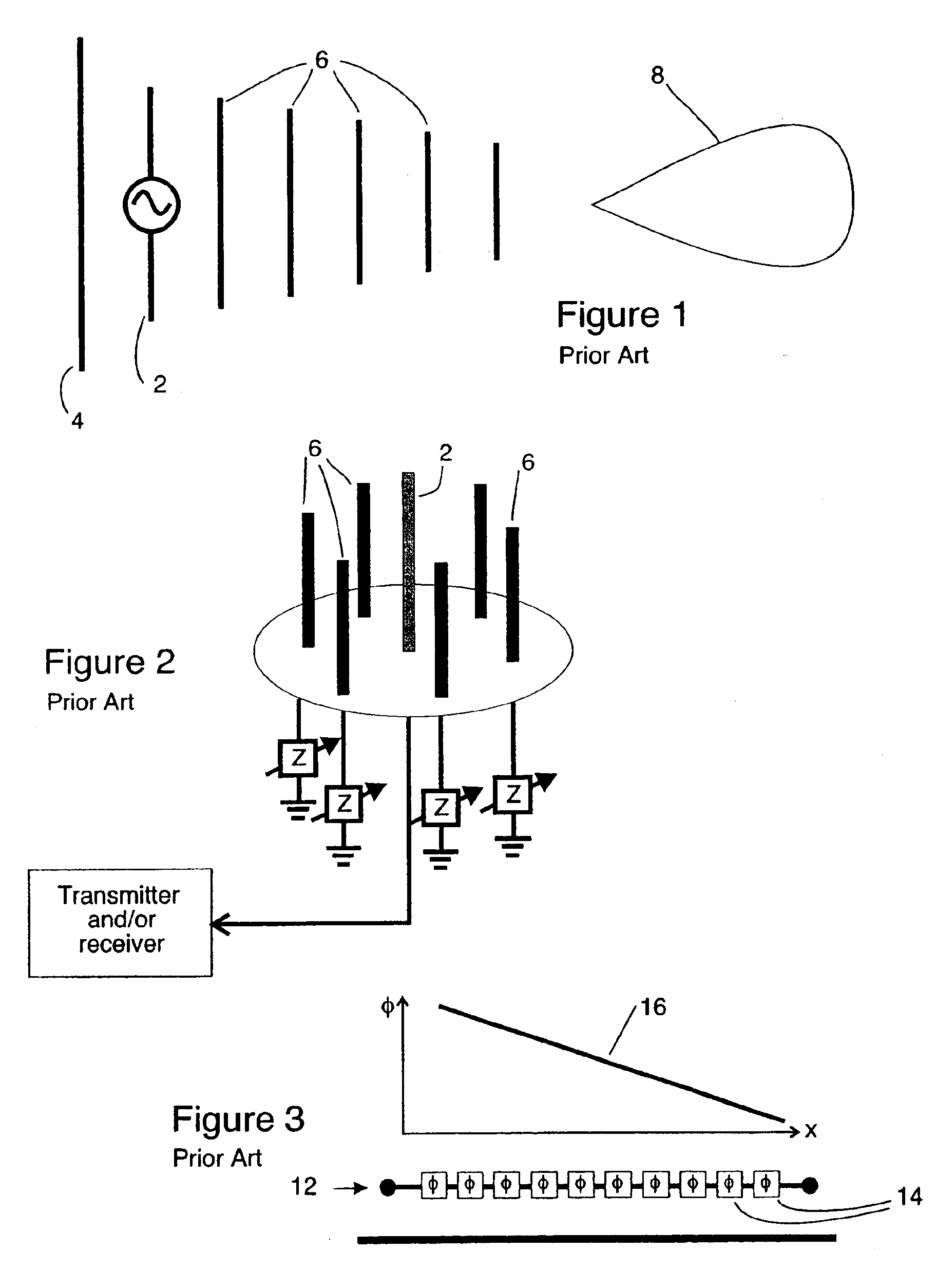
[0052]It has been known for decades that parasitic antenna elements can also be used for beam forming, such as the popular Yagi-Uda array 10, shown in FIG. 1. This array 10 consists of three kinds of elements: (1) a single driven element 2, (2) a reflector element 4, which is typically longer or has a lower resonance frequency than the driven element 2, and (3) a series of director elements 6, which are typically shorter or have a higher resonance frequency than the driven element 2.

[0053]The Yagi-Uda array 10 works as follows: The driven element 2 radiates power, which is received by all of the parasitic elements, which comprise the reflector element 4 and the director elements 6. These parasitic elements 4, 6 re-radiate the power with a phase that depends on the resonance frequency of the parasitic elements with respect to the frequency of the driven element 2. The radiation from the parasitic elements 4, 6 adds with the radiation from the driven element 2 with the appropriate pha...


PUM


Abstract

An antenna having at least one main element and a plurality of parasitic elements. At least some of the elements have coupling elements or devices associated with them, the coupling elements or devices being tunable to thereby control the degree of coupling between adjacent elements. Controlling the degree of coupling allows a lobe associated with the antenna to be steered.

Description

CROSS REFERENCE TO RELATED APPLICATIONS AND PATENTS[0001]This application claims the benefit of U.S. Provisional Patent application No. 60 / 470,027 filed May 12, 2003, the disclosure of which is hereby incorporated herein by reference.[0002]This application is also related to the disclosure of U.S. Provisional Patent Application Ser. No. 60 / 470,028 also filed on May 15, 2003 and entitled “Steerable Leaky Wave Antenna Capable of both Forward and Backward Radiation”, the disclosure of which is hereby incorporated herein by reference. It is also related to a subsequently filed and related non-provisional application, which application was filed on the same date as this application (see U.S. patent application Ser. No. 10 / 792,412) and which application is also entitled “Steerable Leaky Wave Antenna Capable of both Forward and Backward Radiation”, the disclosure of which is hereby incorporated herein by reference.[0003]This application is also related to the disclosure of U.S. Provisional...

Claims


Application Information

Patent Timeline
Patent Type & Authority Patents(United States)
IPC IPC(8): H01Q9/00H01Q3/26H01Q3/44H01Q3/46H01Q9/04H01Q13/20H01Q15/00H01Q19/32H01Q21/06H01Q23/00
CPCH01Q3/26H01Q3/443H01Q3/46H01Q9/0442H01Q15/008H01Q19/32H01Q21/061H01Q23/00H01Q15/002H01Q13/20
Inventor SIEVENPIPER, DANIEL F.
Owner HRL LAB
Why Eureka
Try Eureka