Column driver for OLED display

a technology of organic light-emitting diodes and column drivers, which is applied in the direction of instruments, static indicating devices, etc., can solve the problems of large feature size, high cost, and inability to meet the requirements of a dual-scan scheme, and achieve the effect of reducing the cost of processing technology and reducing the cost of processing

Inactive Publication Date: 2006-06-27
AIMS
View PDF35 Cites 1 Cited by
  • Summary
  • Abstract
  • Description
  • Claims
  • Application Information

AI Technical Summary

Benefits of technology

[0012]Another object of the present invention to provide a column ...

Problems solved by technology

The lifetime of an OLED device, however, deteriorates as current and voltage levels increase.
In addition, in order to make the design withstand higher voltage application, a design rule of larger feature size as well as an expensive processing technology is needed.
There are, however, several problems w...

Method used


Image

  • Column driver for OLED display
  • Column driver for OLED display
  • Column driver for OLED display

Examples


Embodiment Construction

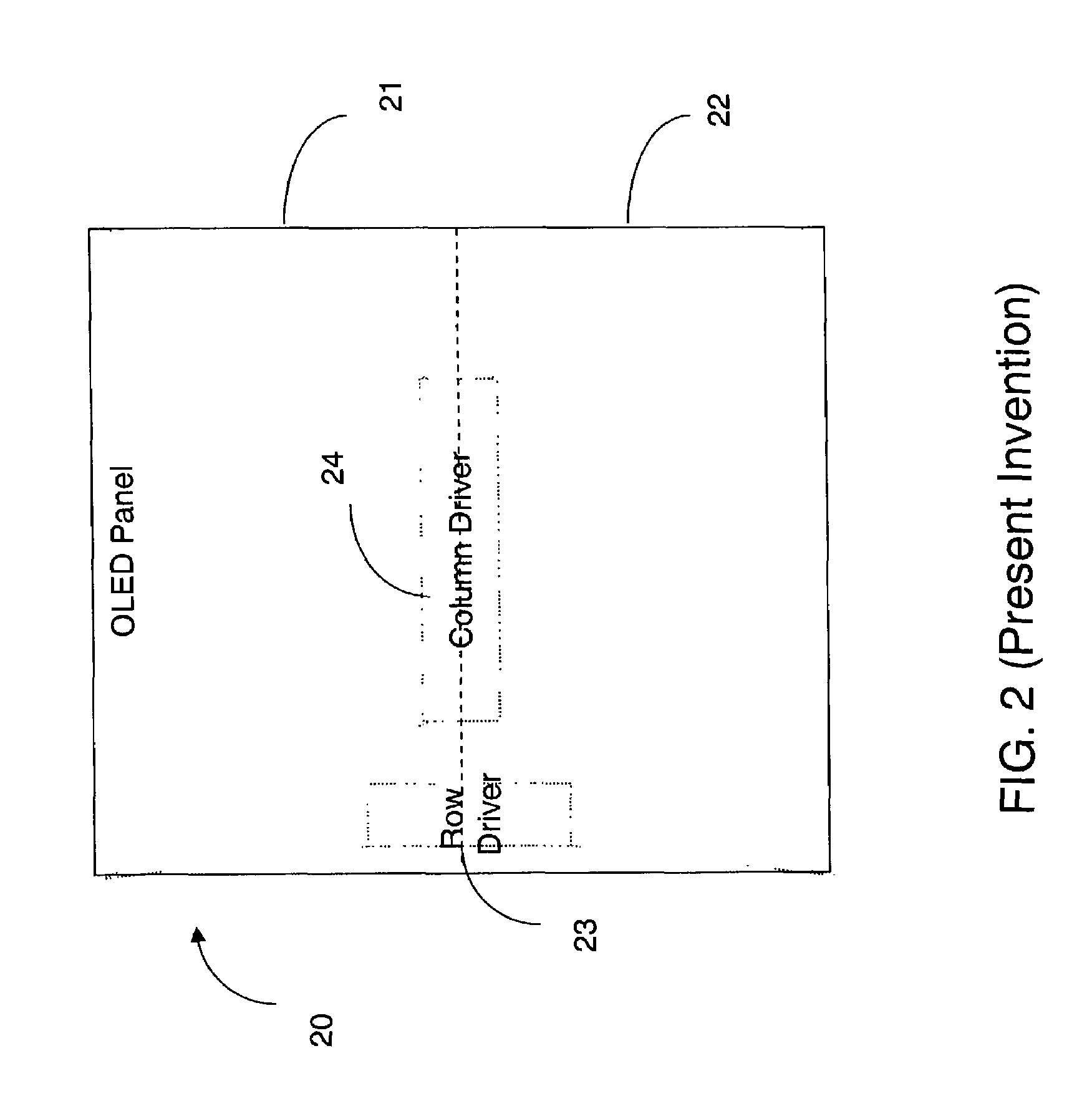
[0020]FIG. 2 shows a scheme of the present invention using one column driver for driving a dual-scan OLED display 20. In addition to a row driver 23 for selectively activating a row electrode, a single column driver 24 drives both the upper OLED panel 21 and the lower OLED panel 22.

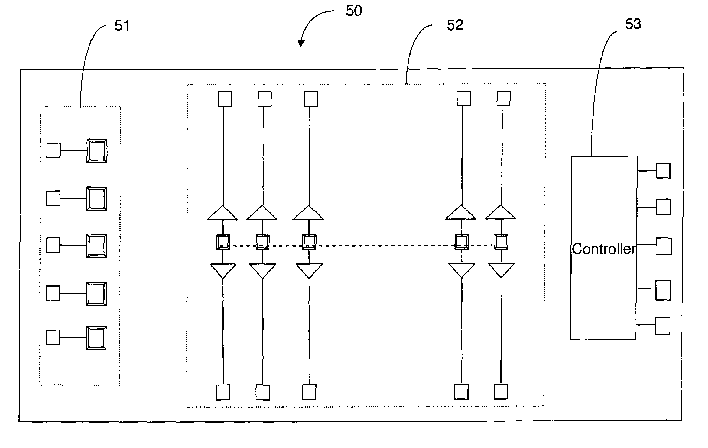
[0021]FIG. 3 shows the column driver 24 of FIG. 2 in further detail. For each column, there is a current source 31 that has two output circuitry: one 32 for driving the column electrode in the upper panel through a pad such as 34 and another 33 for driving the column electrode in the lower panel through a pad such as 35.

[0022]Although a preferred embodiment of the column driver of the present invention has been shown to be used in conjunction with the dual-scan scheme, the column driver may also be used in conjunction with the single-scan scheme where the panel is not divided into two. For example, pad 34 of FIG. 3 may be connected to a column electrode while pad 35 of FIG. 3 is connected to the next colu...


PUM


Abstract

A single-chip column driver for organic light emitting diode (OLED) display is disclosed. Instead of using two column drivers for dual scan, the present invention uses one column driver driving both the upper and the lower OLED panels. The column driver has a two set of output circuitry: one for driving the upper panel and the other for driving the lower panel. The single chip solution of the present invention eliminates the problem of display uniformity without increasing the part count. The invention also enables independent control of RGB without further increasing the part count.

Description

RELATED APPLICATION[0001]This application claims the benefit of co-pending U.S. Provisional Application Ser. No. 60 / 325,304, filed Sep. 26, 2001, entitled “Column Driver for OLED Display.”BACKGROUND OF THE INVENTION[0002]1. Technical Field[0003]This invention in general relates to semiconductor circuits. More specifically, this invention relates to circuits for driving columns of an organic light emitting diode (OLED) displays.[0004]2. Description of the Related Art[0005]Recently, much progress has been made in organic light emitting diode (OLED). An OLED display is made up of rows and column electrodes for selectively activating the OLED at each intersection. The row and column electrodes are driven by a row driver and a column driver, respectively. The row electrodes are scanned in sequence to refresh the display image.[0006]As the OLED display becomes larger with an increased number of rows, the row scan frequency should increase, which reduces the time during which electric curr...

Claims


Application Information

Patent Timeline
IPC IPC(8): G09G3/32
CPCG09G3/3208G09G3/3275G09G2300/0408G09G2320/043G09G2310/0221G09G2320/02G09G2320/0223G09G2300/0426
Inventor AHN, SUNG TAELEE, KEUNMYUNGAHN, DAE YOUNGPARK, TAE KWANG
Owner AIMS
Why Eureka
Try Eureka