
Dual scan method for detecting a fibre misalignment in an elongated structure

a technology of elongated structure and fibre misalignment, which is applied in the field of composite structures, can solve the problems of insufficient visual inspection, insufficient visual inspection, and inability to detect fibre misalignment, and achieve the effects of rapid and cost-effective, and reducing the likelihood of fibre misalignmen

Active Publication Date: 2021-07-06
LM WIND POWER US TECH APS
View PDF8 Cites 0 Cited by
  • Summary
  • Abstract
  • Description
  • Claims
  • Application Information

AI Technical Summary

Benefits of technology

The present invention provides a method for detecting fibre misalignments in wind turbine blades or components thereof in a more targeted and cost-effective way than known methods. By initially scanning the surface of the structure, the method enables the identification of regions with an increased likelihood of fibre misalignment, which can then be further examined using penetrating radiation. This approach allows for detecting and locating fibre misalignments in the depth of the structure, resulting in savings in repair time and cost. Ultimately, this method improves the reliability of the wind turbine blade by reducing the likelihood of failures.

Problems solved by technology

Any fibre misalignment can result in a failure or breakage of the wind turbine blade.
Such visual inspection is not sufficient, since it allows only detecting fibre misalignments that are present on the surface of the elongated structure.
Also, such visual inspection may be time-consuming and inefficient with respect to small surface undulations that might be missed during visual inspection.
Fibre misalignments that are not on the surface only, such as deeper fibre misalignment or hidden fibre misalignments are equally detrimental to the reliability of the elongated structure.
Ultrasonic testing methods have not proven sufficiently useful as a method to identify and quantify wrinkles.
Further, the sensors operate at wavelengths that do not enable appropriate detection or quantification of the wrinkles.
While this method was found adequate in identifying deeper fibre misalignment or hidden fibre misalignments it may be time-consuming and expensive to apply it to an entire wind turbine blade structure.

Method used


Image

  • Dual scan method for detecting a fibre misalignment in an elongated structure
  • Dual scan method for detecting a fibre misalignment in an elongated structure
  • Dual scan method for detecting a fibre misalignment in an elongated structure

Examples


Embodiment Construction

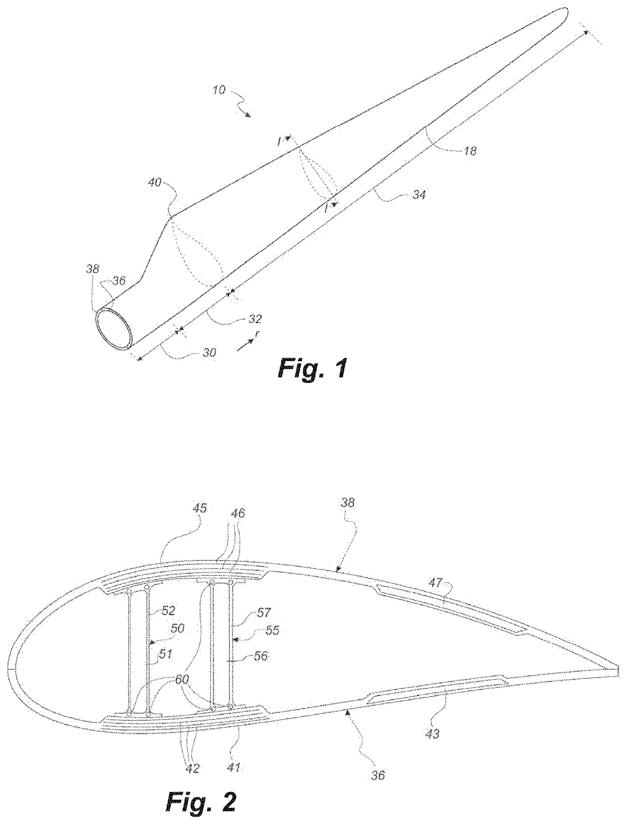
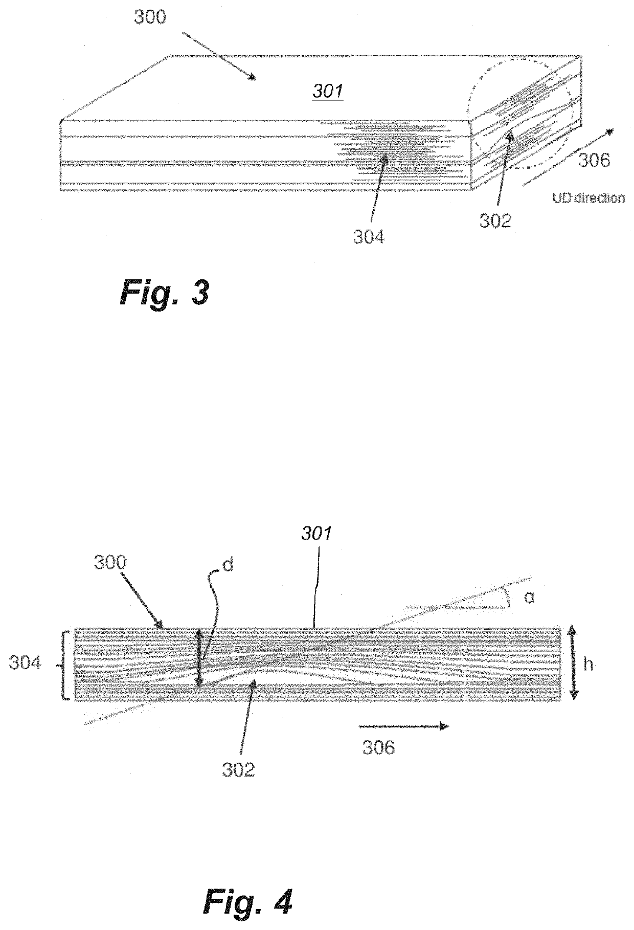
[0043]As stated in the background, there is a need for a method for detecting fibre misalignments, such as identifying hidden (below the surface) fibre misalignments in an efficient and non-destructive manner. The invention relates to a method for detecting a fibre misalignment in an elongated structure, such as a wind turbine blade component, an airplane wing, or a vessel hulls. The invention is particularly suited for large elongated structures where a non-destructive inspection is highly valued due to the costs occurred by a destructive inspection. Accordingly, the invention preferably relates to wind turbine blades as well as intermediary elongated structures having a total length of at least 30 metres, 40 metres, 45 metres, or 50 metres and / or a thickness of 1-80 mm. Accordingly, the invention preferably relates to wind turbine blades comprising materials having different densities so that x-ray radiation can reveal misalignments.

[0044]Fibre misalignment refers herein to a misa...


PUM

PropertyMeasurementUnit
wavelengthaaaaaaaaaa
angleaaaaaaaaaa

Abstract

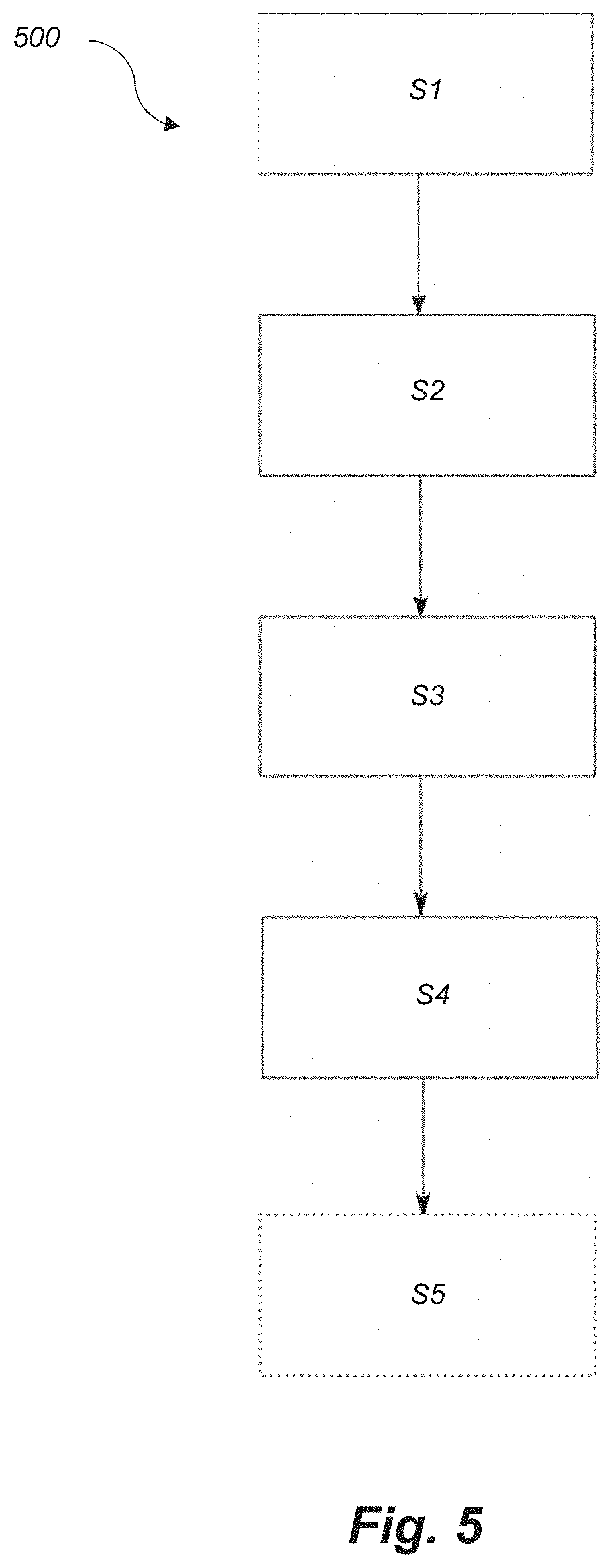
The present disclosure relates to a method for detecting a fibre misalignment in an elongated structure, such as a wind turbine blade component. The elongated structure has a length along a longitudinal direction and comprises a plurality of stacked reinforcing fibre layers. The plurality of fibre layers comprises fibres having an orientation aligned, unidirectionally, substantially in the longitudinal direction. The method comprises scanning a surface of the elongated structure for identifying one or more surface irregularities, selecting one or more regions of interest comprising said one or more surface irregularities, examining said region of interest using penetrating radiation, and determining a position and / or size of the fibre misalignment based on said examining step.

Description

[0001]This is a National Phase Application filed under 35 U.S.C. 371 as a national stage of PCT / EP2018 / 063359, filed May 22, 2018, an application claiming the benefit of European Application No. 17172448.7, filed May 23, 2017, the content of each of which is hereby incorporated by reference in its entirety.FIELD OF THE INVENTION[0002]The present disclosure pertains to the field of composite structures, and more specifically to fibre misalignment in elongated structures. The present disclosure relates to a method for detecting a fibre misalignment in an elongated structure, to a method of manufacturing an elongated structure and to an elongated composite structure obtainable by said method.BACKGROUND OF THE INVENTION[0003]Elongated structures such as wind turbine blades, airplane wings, and vessel hulls can be manufactured using fibre reinforcing material. The fibre reinforcing material is often stacked forming a plurality of stacked layers, while aligning an orientation of the fibre...

Claims


Application Information

Patent Timeline
Patent Type & Authority Patents(United States)
IPC IPC(8): G01N23/04G01N23/18G01N23/201B29C70/30B29C70/54G01B11/30G01N23/044G01N23/083B29K31/00B29K67/00B29K307/04B29K309/08B29L31/08
CPCG01N23/18B29C70/30B29C70/54G01B11/30G01N23/044G01N23/083G01N23/201B29K2031/00B29K2067/00B29K2307/04B29K2309/08B29L2031/085G01N2223/054G01N2223/1016G01N2223/305G01N2223/41G01N2223/421G01N2223/615G01N2223/63G01N2223/645G01N2223/646G01B11/24G01B15/045G01B11/272Y02E10/72Y02P70/50
Inventor JESPERSEN, KLAVSNIELSEN, LARSLAURIDSEN, TORSTEN
Owner LM WIND POWER US TECH APS
Learn More