Reduction of scan time in imaging mass spectrometry

a mass spectrometry and scan time technology, applied in the field of mass spectrometry, can solve the problems of compromising the quality of mass spectral data, requiring substantial modification of hardware components, and requiring several hours or even days of instrument time to generate mass spectral images, so as to reduce the spacing of target regions, improve the likelihood of locating highly differentiated areas, and significantly improve the effect of efficiency

Inactive Publication Date: 2007-06-21
THERMO FINNIGAN
View PDF6 Cites 48 Cited by
  • Summary
  • Abstract
  • Description
  • Claims
  • Application Information

AI Technical Summary

Benefits of technology

[0007] The second technique involves a multi-step imaging process, wherein an initial tissue imaging scan is performed to obtain a mass spectral image at relatively low resolution (i.e., with relatively large average spacing between adjacent target regions) in order to identify areas of interest within the tissue sample, for example, areas that have highly differentiated analyte abundances. The target regions may be randomly distributed to increase the likelihood of locating the highly differentiated areas within the tissue sample. A subsequent scan of the areas of interest is performed with reduced target region spacing to obtain high-resolution mass spectral imaging of the areas of interest. This multi-scan technique is significantly more efficient and less time-consuming than the prior art technique because high-resolution imaging is only performed on areas of interest rather than throughout the entire tissue area.

Problems solved by technology

One of the major obstacles to the widespread use of tissue imaging as a standard industrial analytical technique is the lengthy analysis (scan) time required to obtain a mass spectral image.
Generation of a mass spectral image for a typical tissue sample of 1cm2 can require several hours or even days of instrument time.
However, such approaches may compromise the quality of the mass spectral data and / or require substantial modification of the hardware components to implement.

Method used


Image

  • Reduction of scan time in imaging mass spectrometry
  • Reduction of scan time in imaging mass spectrometry
  • Reduction of scan time in imaging mass spectrometry

Examples


Embodiment Construction

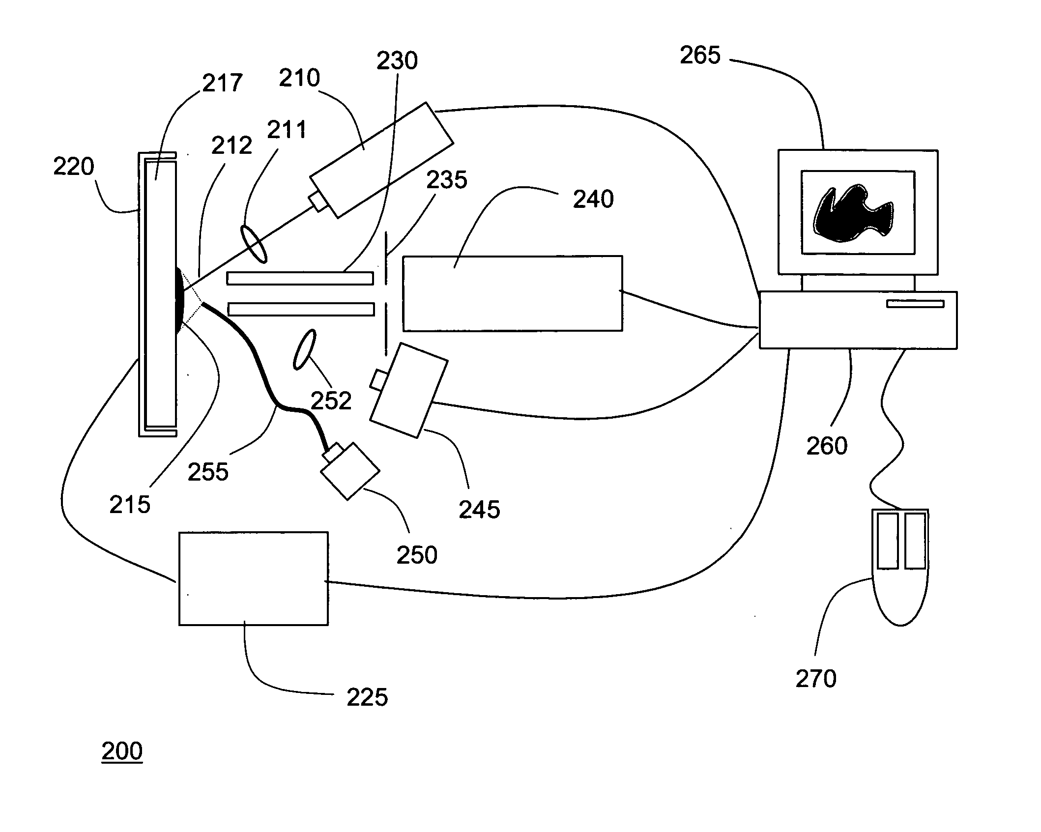
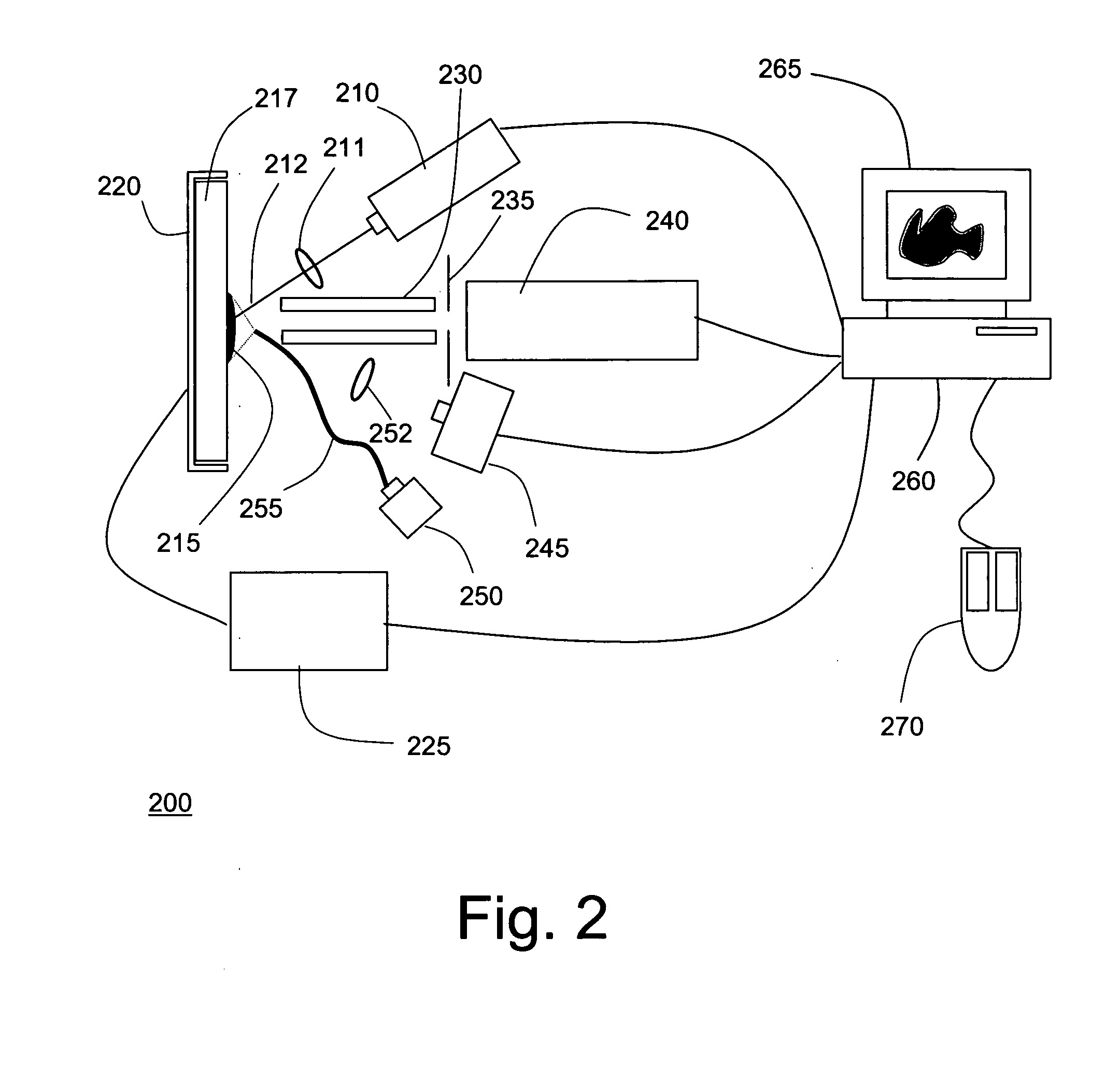
[0020]FIG. 2 is a symbolic diagram showing the components of an exemplary mass spectrometer 200 in which the techniques of the present invention may be implemented. As shown, MS system 200 includes a laser 210 positioned to direct a pulsed beam of radiation 212 onto a portion of a tissue sample 215 arranged on sample plate 217. A sample plate holder 120 is provided with a positioning mechanism, such as an X-Y stage, to align the laser spot (the impingement area of the laser beam) with a selected region of sample plate 115. Sample plate holder 220 is typically positioned in the X-Y plane (the plane defined by sample plate 217) by means of stepper motors or similar actuators, the operation of which is precisely controlled by signals transmitted from controller 225. The radiation emitted by laser 210 will typically be focused by at least one lens or equivalent optical element 211 disposed between the laser and the tissue sample. In alternate configurations, alignment of the laser spot ...


PUM

PropertyMeasurementUnit
thicknessaaaaaaaaaa
distanceaaaaaaaaaa
mass spectrometric analysisaaaaaaaaaa

Abstract

Techniques are disclosed for reducing scan times in mass spectral tissue imaging studies. According to a first technique, a tissue imaging boundary is defined that closely approximates the edges of a tissue sample. According to a second technique, a low-resolution scan is performed to identify one or more areas of interest within the tissue sample, and the identified areas of interest are subsequently scanned at higher resolution.

Description

FIELD OF THE INVENTION [0001] The present invention relates generally to the field of mass spectrometry, and more particularly to techniques and apparatus for analyzing the spatial distribution of substances in a tissue sample using a mass spectrometer. BACKGROUND OF THE INVENTION [0002] Mass spectrometry has become an essential analytical tool for the identification and quantification of both small molecules (e.g., drugs and their metabolites) and large molecules (e.g., polypeptides). Recently, there has been growing interest in the use of mass spectrometry for tissue imaging, which is the generation of spatially resolved maps depicting the distribution of one or more substances in a tissue sample. This technique has been described in numerous prior art references including, for example, U.S. Pat. Nos. 5,808,300 and 6,756,586, both to Caprioli. Mass spectral tissue imaging has a number of highly promising applications, including as a tool for the study of the metabolism and distrib...

Claims


Application Information

Patent Timeline
Patent Type & Authority Applications(United States)
IPC IPC(8): G01N24/00
CPCY10T436/24H01J49/0004
Inventor BUI, HUY A.
Owner THERMO FINNIGAN
Why Eureka
Try Eureka