
Mounting apparatus for disk drive devices

a technology for mounting apparatuses and disk drives, which is applied in the direction of electric apparatus casings/cabinets/drawers, furniture parts, instruments, etc., can solve the problems of inconvenient assembly operation, unduly painstaking and time-consuming way of mounting disk drive brackets, and inconvenient assembly operation. , to achieve the effect of convenient mounting of disk drive devices

Inactive Publication Date: 2006-06-27
HONG FU JIN PRECISION IND (SHENZHEN) CO LTD +1
View PDF8 Cites 30 Cited by
  • Summary
  • Abstract
  • Description
  • Claims
  • Application Information

AI Technical Summary

Benefits of technology

The present invention provides a mounting apparatus for conveniently mounting disk drive devices to a computer enclosure. The apparatus includes a bracket, an operation member, and a pair of rails. The bracket has two sidewalls with retaining holes, and the operation member is slidably mounted on the second sidewall. The operation member has a hook that corresponds to a protrusion on the bracket. Each rail has locating posts that correspond to the retaining holes. The operation member is in a holding position to secure the locating posts and the hook in place, and it can be released to disassemble the device. The technical effect of this invention is to provide a simple and efficient way to mount disk drive devices in a computer enclosure.

Problems solved by technology

However, this way of securing the disk drive brackets is unduly painstaking and time-consuming.
Disassembly of the disk drive brackets is similarly painstaking and time-consuming.
Thus makes the assembly operation inconvenient, and increases the risk of accidental damage to other components such as sensitive electronic components inside the computer enclosure.

Method used


Image

  • Mounting apparatus for disk drive devices
  • Mounting apparatus for disk drive devices
  • Mounting apparatus for disk drive devices

Examples


Embodiment Construction

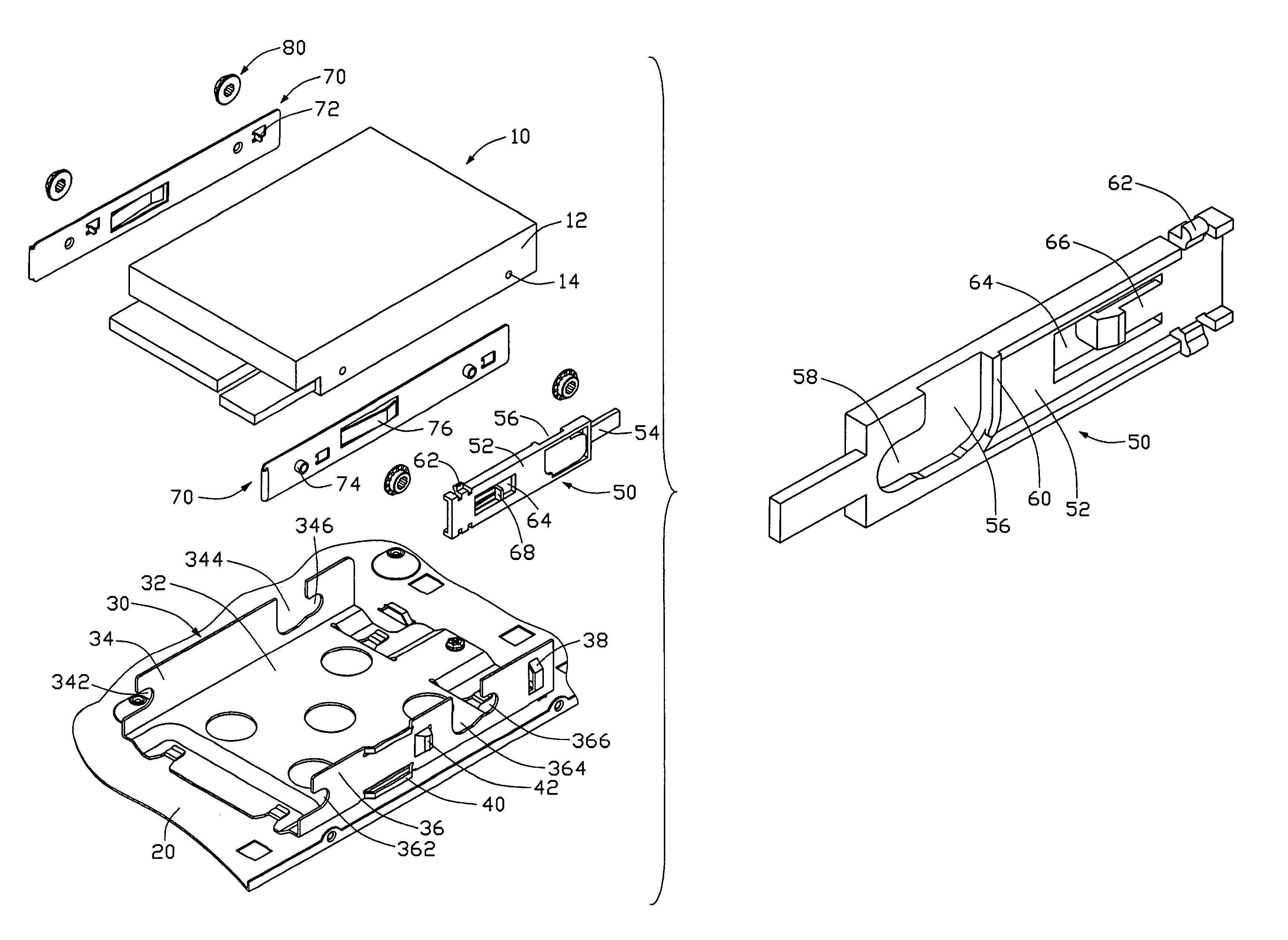
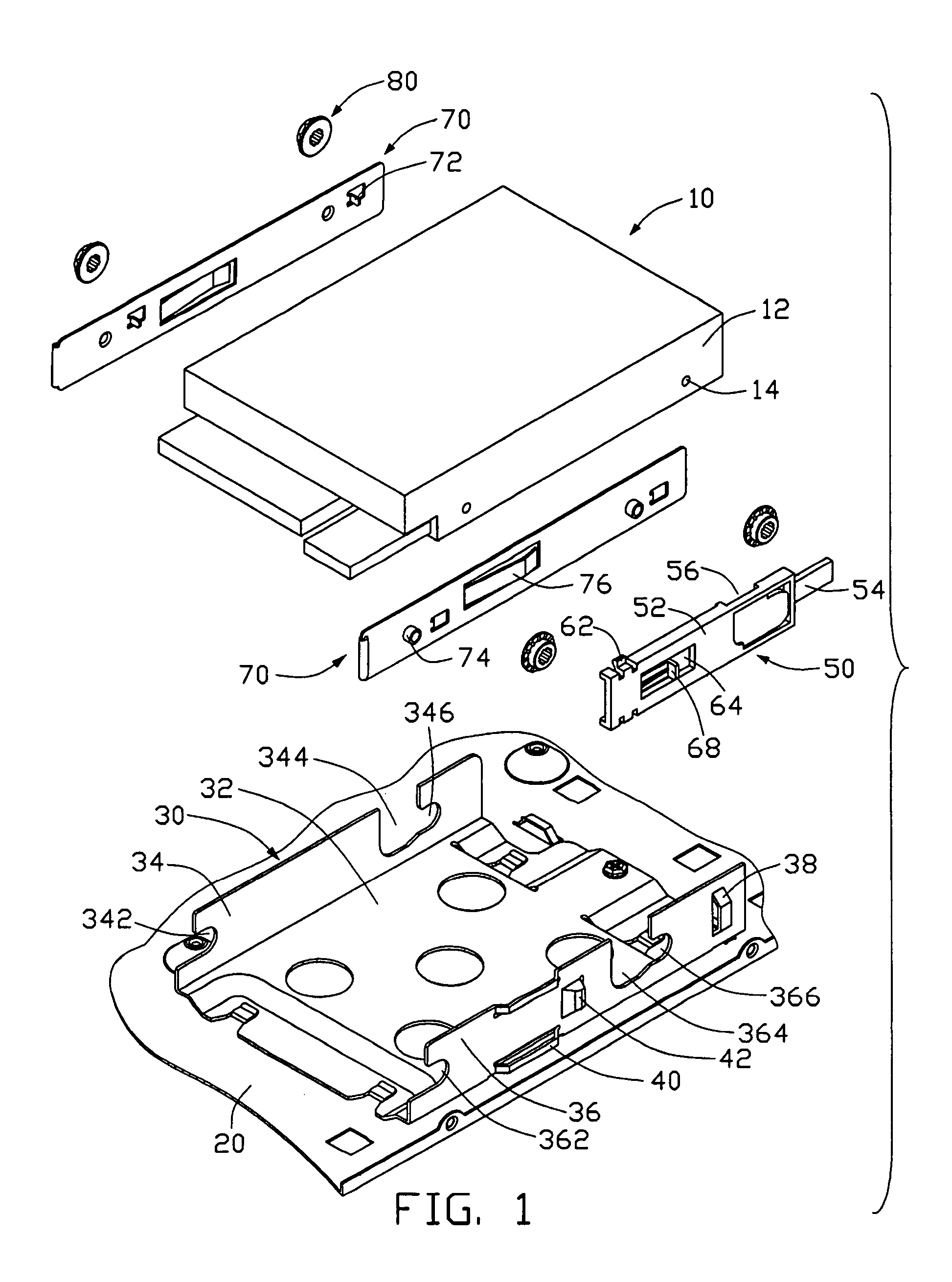
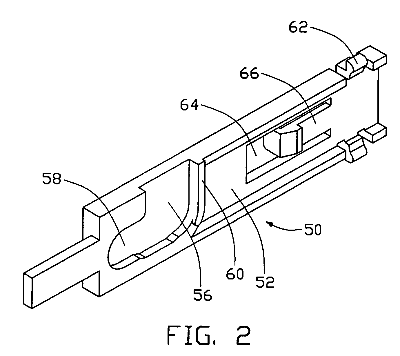
[0016]Referring to FIGS. 1 and 2, a mounting apparatus in accordance with a preferred embodiment of the present invention for securing a disk drive 10 to a computer enclosure (a mounting wall 20 of the enclosure shown only), comprises a bracket 30, an operation member 50, a pair of rails 70 and four rubber gaskets 80.

[0017]The disk drive 10 has two parallel sidewalls 12. Two fixing holes 14 are defined in each of the sidewalls 12.

[0018]The bracket 30 comprises a bottom wall 32 mounted on the mounting wall 20 of the computer enclosure, a first sidewall 34 and a second sidewall 36 bent upwardly from opposite sides of the bottom wall 32. The first sidewall 34 and the second sidewall 36 each define a first retaining hole 342, 362 at one corresponding ends, a vertical slot 344, 366 at opposite ends. Two second retaining hole 346, 366 are defined at the ends of the slots 344, 366 of the first sidewall 34 and second sidewall 36 respectively. The second sidewall 36 forms a retaining portion...


PUM


Abstract

A mounting apparatus for disk drive devices includes a bracket (30), an operation member (50), and a pair of rails (70). The bracket has a first sidewall (34) and a second sidewall (36) each defining a first retaining hole (342, 362) and a second retaining hole (346, 366). The second sidewall has a protrusion (42). The operation member is slidably mounted on the second sidewall. A hook (66) is formed on the operation member corresponding to the protrusion of the bracket. Each rail protrudes two locating posts (74) corresponding to the first and second retaining holes. In assembly, the operation member is in a holding position in which the locating posts of the rails are retained in the corresponding first and second retaining holes and the hook clasps the protrusion. In disassembly, the operation member is in a released position, and the hook is released from the protrusion.

Description

BACKGROUND OF THE INVENTION[0001]1. Field of the Invention[0002]The present invention relates to mounting apparatuses, and particularly to a mounting apparatus for mounting disk drive devices to computer enclosures.[0003]2. Description of Related Art[0004]In the enclosure of a typical personal computer, there are generally two disk drive brackets mounted therein. Usually, a variety of disk drives are received in the disk drive brackets, which are then secured into the enclosure. There are many ways to secure the disk drive brackets in the enclosure. One way is by using screws. A pair of joining edges is formed on opposite sides of a bottom of a lower disk drive bracket. Fixing holes are defined in the joining edges. The lower disk drive bracket is secured to a bottom of an upper disk drive bracket by screws. However, this way of securing the disk drive brackets is unduly painstaking and time-consuming. Disassembly of the disk drive brackets is similarly painstaking and time-consumin...

Claims


Application Information

Patent Timeline
Patent Type & Authority Patents(United States)
IPC IPC(8): G06K1/16G06F1/18
CPCG06F1/187G06F1/184
Inventor CHEN, YUN LUNGSHI, CHUAN MINXU, ZHOU
Owner HONG FU JIN PRECISION IND (SHENZHEN) CO LTD
Learn More