Heat-moisture exchanger with aerosol by-pass

a technology of heat-moisture exchanger and air by-pass, which is applied in the direction of indirect heat exchanger, respirator, light and heating apparatus, etc., can solve the problems of complex devices and high production costs

Active Publication Date: 2006-07-04
WALDO JR JAMES V +1
View PDF5 Cites 32 Cited by
  • Summary
  • Abstract
  • Description
  • Claims
  • Application Information

AI Technical Summary

Benefits of technology

[0004]The present invention provides the same effect as provided by U.S. Pat. No. 6,792,946, but achieves that same effect with a less expensive arrangement of parts. A first and a second housing is engaged to a rotatable middle housing. A heat-moisture exchange material is mounted within the middle housing and a tube passes through an opening in the heat-moisture exc

Problems solved by technology

However, the device is compl

Method used


Image

  • Heat-moisture exchanger with aerosol by-pass
  • Heat-moisture exchanger with aerosol by-pass
  • Heat-moisture exchanger with aerosol by-pass

Examples


Embodiment Construction

[0011]Throughout the following detailed description, the same reference numerals refer to the same elements in all figures.

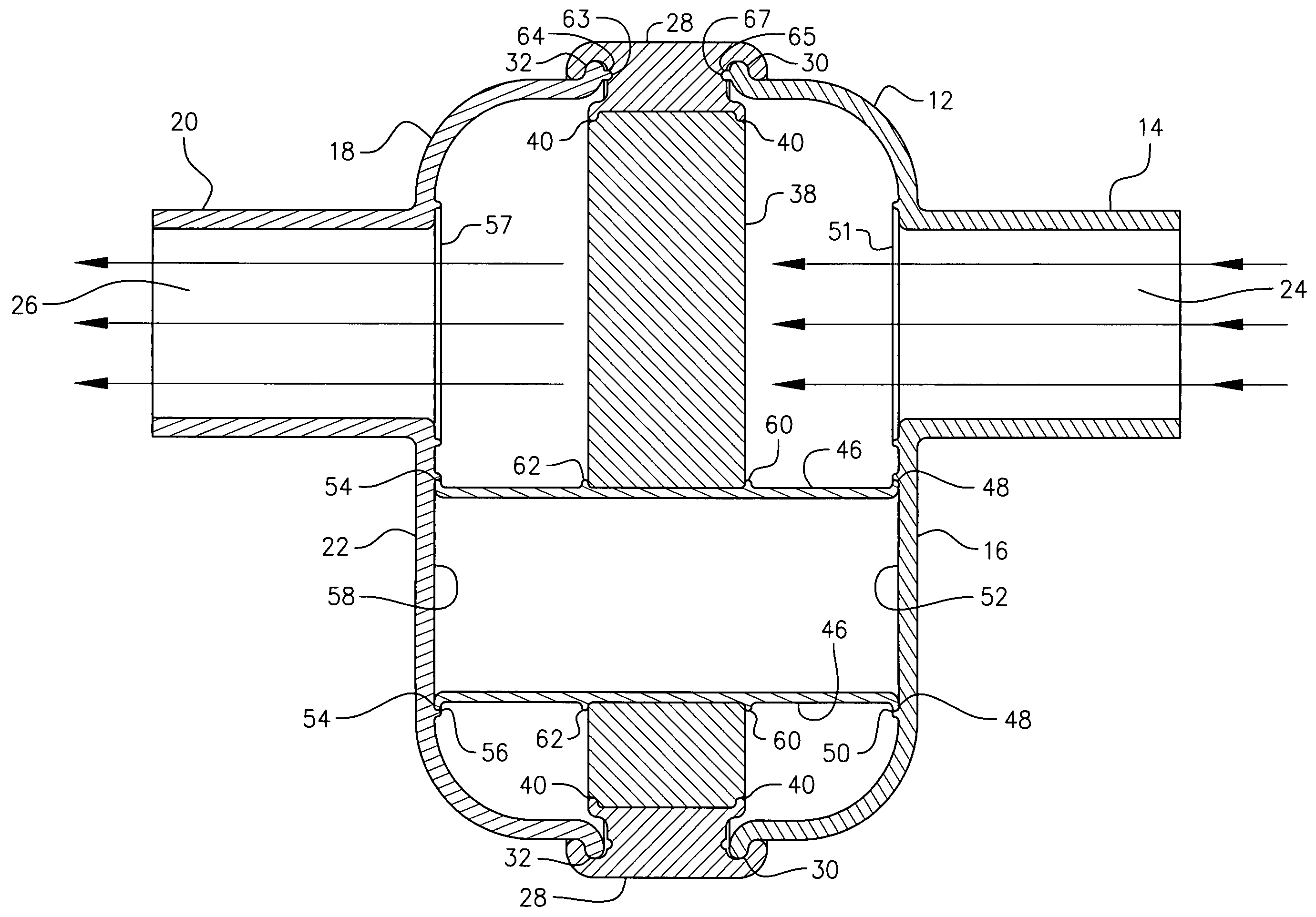
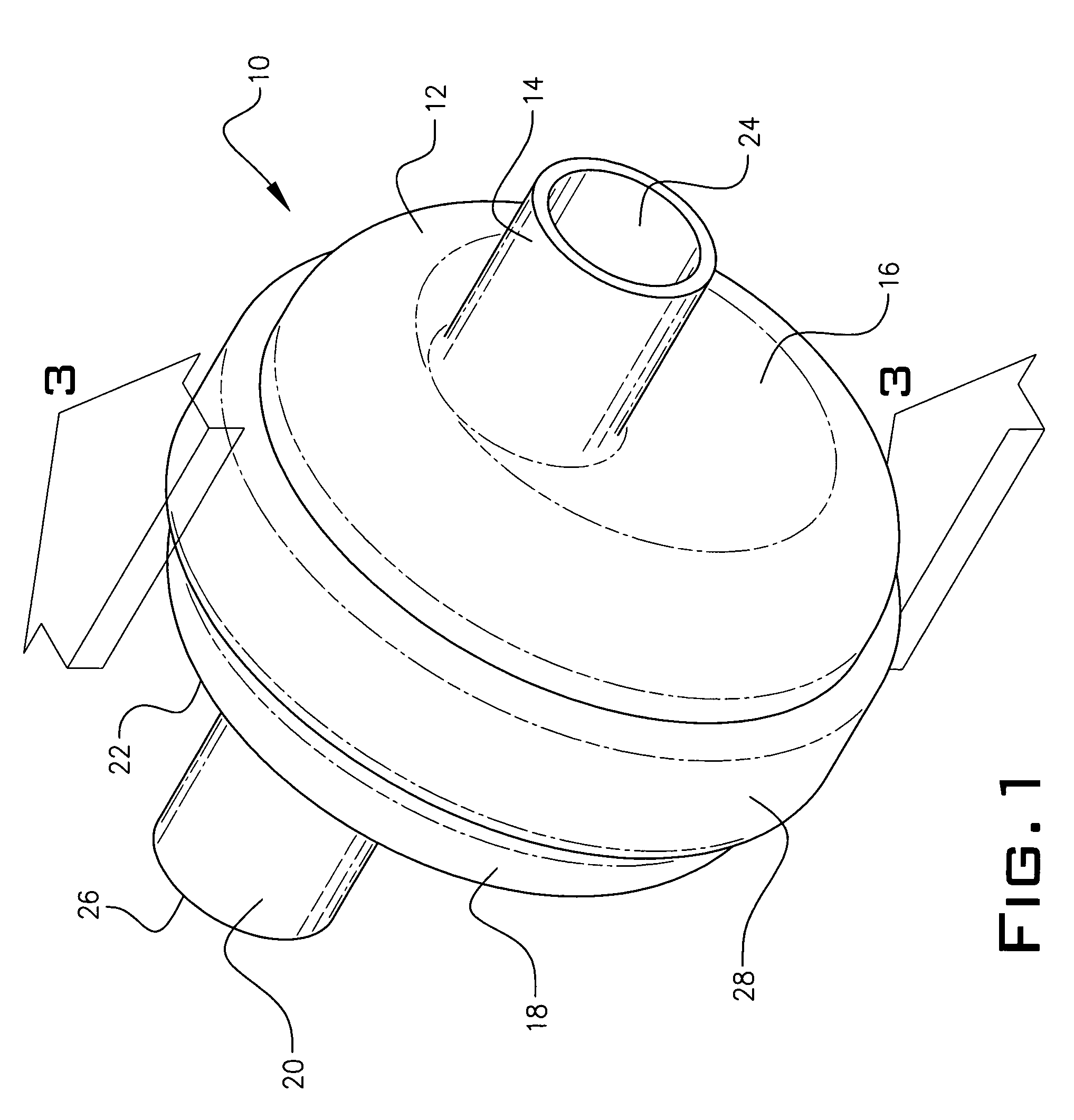
[0012]Referring to FIG. 1, the apparatus 10 of this invention has a first housing 12 with an integral conduit 14 passing though exterior side 16 of housing 12. Likewise, a second housing 18 has an integral conduit 20 passing though an exterior side 22. A passageway 24 in conduit 14 leads inwardly though the exterior side 22 of housing 12 and ends at groove 51. A like passageway 26 in conduit 20 leads outwardly through the exterior side 22 of housing 18 and ends at groove 57. A cylindrical rotatable middle housing 28 is interposed between the first and second housing.

[0013]Referring to FIG. 2, the first housing 12 and second housing 18 each have an annular interior lip 30 and 32 respectively. Rotatable middle housing 28 has a groove 34 on an outer edge of a first side which slides over lip 30 on first housing 12. Likewise, housing 28 has a groove 36 on an outer e...


PUM


Abstract

A first and second housing is joined together by a middle housing rotatable with respect to the first and second housing. The first and second housings have conduits passing through exterior walls and an annular ring on an inside wall together with an annular interior edge rotatably joined to first and second side rim channels of the middle housing. A heat-moisture exchanger material having an annular opening through which a tube passes is mounted within the middle housing so that in a first rotatable position air and moisture passes through the first and second housing conduits directly and in a second rotatable position must pass through the heat-moisture exchange material.

Description

BACKGROUND OF THE INVENTION[0001]This invention relates to a patient heat-moisture exchanger attached to a nebulizer circuit. More particularly, it refers to a heat-moisture exchanger attached to a patient ventilator circuit, which includes a metered dose inhaler, the exchanger permitting medicament to pass through the heat moisture exchanger without passing through internally mounted filters and without disconnection from the ventilator circuit.DESCRIPTION OF THE PRIOR ART[0002]A heat-moisture exchanger attached to a nebulization device is described in U.S. Pat. No. 6,550,476. This device has a rotatable second housing connected to a first housing. The first housing has at least two chambers enclosing an absorbent material and providing a passageway for an aerosol. The second housing encloses the nebulizer. Valves control the primary gas flow through a passageway to bypass the absorbent material. This device maintains the continuity of a closed ventilator circuit when administering...

Claims


Application Information

Patent Timeline
IPC IPC(8): A62B18/08
CPCA61M16/1045A61M15/0065Y10S128/911
Inventor WALDO, JR., JAMES V.WARNER, CHRISTOPHER D.
Owner WALDO JR JAMES V
Why Eureka
Try Eureka