Method and apparatus for cooling with a phase change material and heat pipes

a phase change material and heat pipe technology, applied in the field of cooling apparatus, can solve the problems of interference with antenna operation, errors and/or inaccuracy during antenna operation, mmic components generating a substantial amount of heat, etc., and achieve the effects of reducing the temperature gradien

Inactive Publication Date: 2006-07-04
RAYTHEON CO
View PDF56 Cites 61 Cited by
  • Summary
  • Abstract
  • Description
  • Claims
  • Application Information

AI Technical Summary

Problems solved by technology

On the other hand, the MMIC components generate a substantial amount of heat.
If not properly cooled, this can interfere with antenna operation.
In particular, temperature gradients across the antenna array must be minimized, because significant temperature gradients introduce phase errors into electrical radio frequency signals within the antenna system, which in turn leads to errors and / or inaccuracies during antenna operation.
Of course, this additional compensation circuitry increases the complexity, cost and weight of the phased array.
Although such a cooling apparatus has been generally adequate for its intended purpose, it has not been satisfactory in all respects.
More specifically, it is not always possible to achieve cooling of a level sufficient to keep temperature gradients across the surface of an antenna system within a desired limit, particularly as operating frequencies increase.
As a result, and as mentioned above, it can be necessary to provide special additional circuitry in the antenna system in order to effect dynamic phase compensation, thereby increasing the complexity, cost and weight of the antenna system.
Further, with respect to antenna systems that are either large and / or high-power systems, the known cooling apparatus is not always capable of providing sufficiently efficient cooling to maintain junctions of the electrical devices at temperatures which are low enough to assure accurate and reliable operation.
One result is a reduction in the accuracy and / or reliability of the overall antenna system.

Method used


Image

  • Method and apparatus for cooling with a phase change material and heat pipes
  • Method and apparatus for cooling with a phase change material and heat pipes
  • Method and apparatus for cooling with a phase change material and heat pipes

Examples


Embodiment Construction

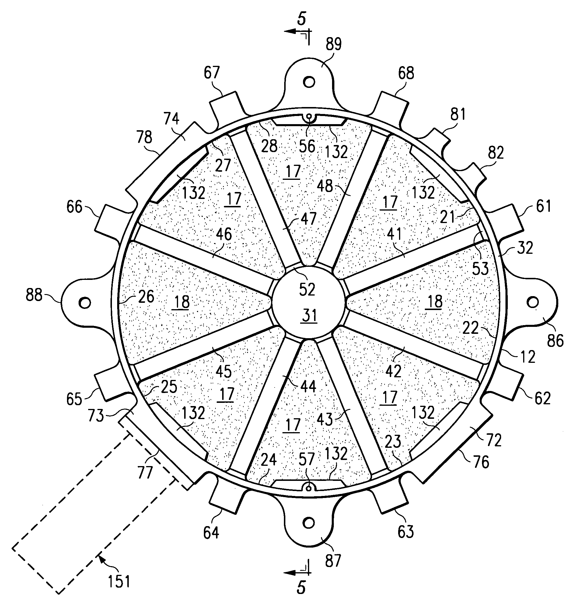
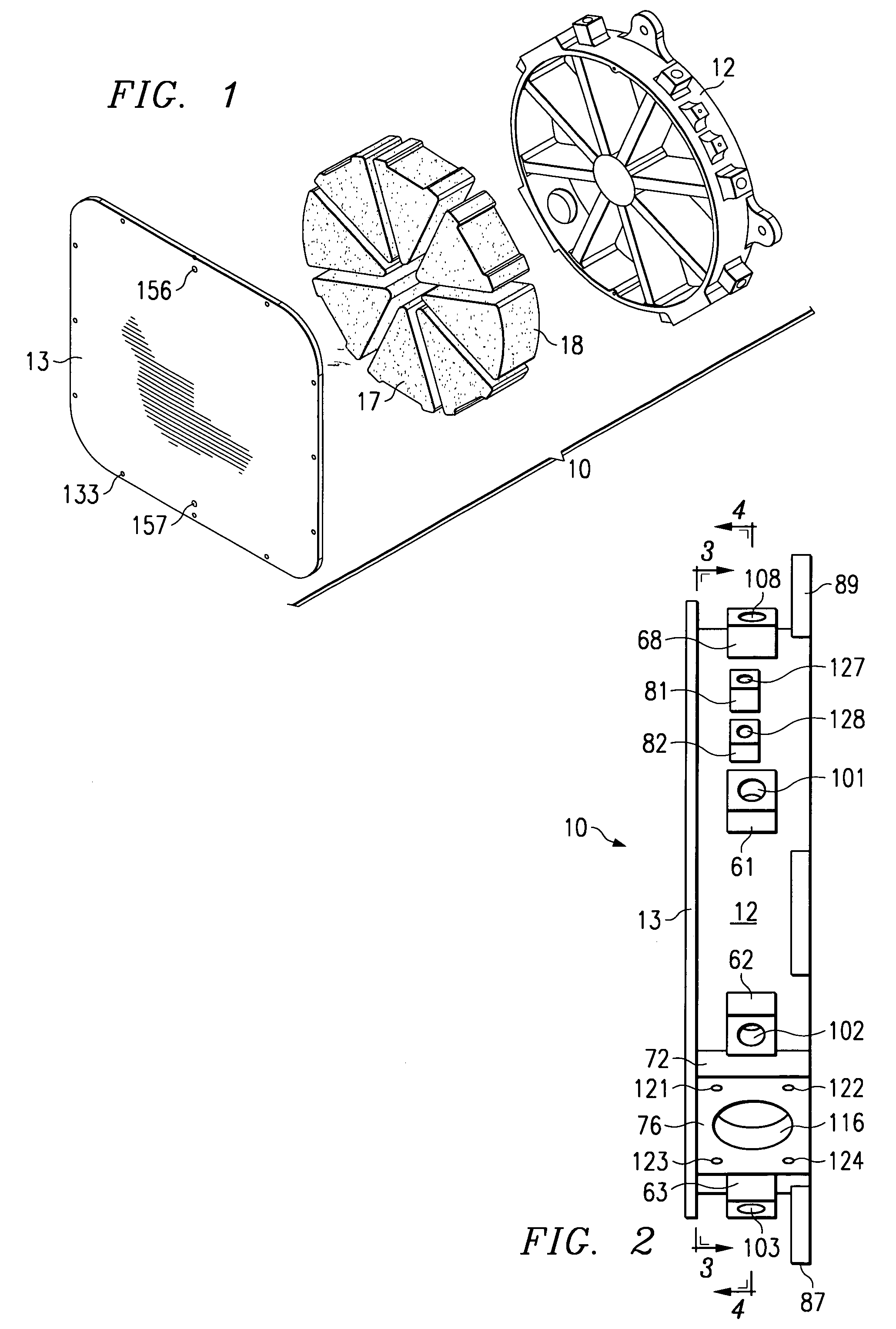
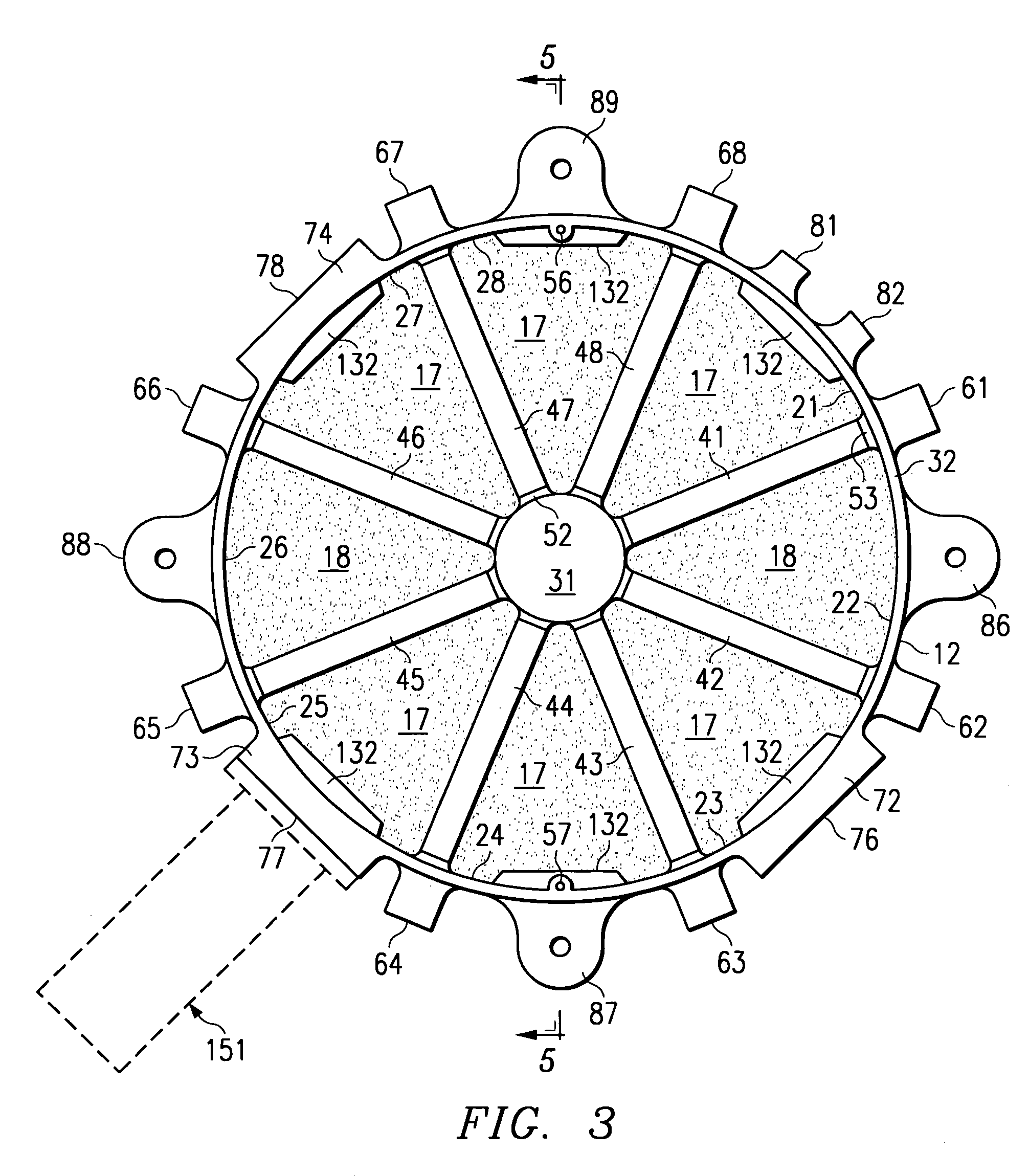
[0019]FIG. 1 is a diagrammatic exploded perspective view of a cooling apparatus 10 which embodies the present invention. The cooling apparatus 10 includes a housing defined by two housing parts 12 and 13. The cooling apparatus 10 further includes a plurality of sector-shaped porous members disposed within the housing, two of which are identified at 17 and 18 in FIG. 1. The housing parts 12–13 and the porous parts 17–18 are all described in more detail later. The cooling apparatus 10 also includes a phase change material, which is disposed in the voids within the porous members 17–18, and is thus not separately visible in FIG. 1. The cooling apparatus 10 also includes three expansion accumulators, which are not depicted in FIG. 1, but which will be described in more detail later.

[0020]In the disclosed embodiment, the housing parts 12 and 13 are each made of a thermally conductive material. The thermally conductive material of the housing parts 12 and 13 is selected to have a coeffici...


PUM


Abstract

A cooling apparatus (10) includes a housing defined by two aluminum parts (12, 13) which are brazed to each other. A plurality of sector-shaped recesses (21–28) are provided within the housing, and collectively define a chamber having a plurality of ribs (41–48) extending therethrough. Each recess contains a sector-shaped piece of porous material (17, 18), which is brazed to surfaces of the housing parts. The remaining space within the chamber is filled with a phase change material. Each of the ribs has therein a respective radially extending opening (101–108) which contains a heat pipe (141). Expansion accumulators (151) are mounted on the housing, and communicate with the chamber therein, in order to accommodate expansion of the phase change material within the chamber as the phase change material is heated.

Description

TECHNICAL FIELD OF THE INVENTION[0001]This invention relates in general to a cooling apparatus and, more particularly, to a cooling apparatus containing a phase change material and suitable for use with a phased array antenna system.BACKGROUND OF THE INVENTION[0002]Phased array antenna systems are frequently used in satellites, for example to provide communication between a satellite and a ground station on the earth. As the satellite goes through its orbit, there are portions of the orbit in which the satellite antenna system can communicate with the ground station, and portions of the orbit in which the curvature of the earth prevents such communication. Consequently, the antenna system is operated during portions of the orbit, and is not operated during other portions of the orbit.[0003]State of the art designs for phased array antenna systems include the use of miniature microwave integrated circuits (MMICs), positioned in close proximity to the antenna elements. The close proxi...

Claims


Application Information

Patent Timeline
Patent Type & Authority Patents(United States)
IPC IPC(8): F28D19/00F28F1/36B64G1/50F25D3/00F28D15/02F28D20/02F28F13/00H01L23/427H01Q1/02H01Q3/30H01Q23/00H05K7/20
CPCB64G1/50B64G1/506F28D15/0275F28D20/02F28D20/023H01Q1/02H05K7/20336F28F13/003H01L2924/0002F25D3/00H01L23/4275Y02E60/145Y10S165/902F28F2275/025F28F2265/12F28F2265/14H01L2924/00Y02E60/14
Inventor HAWS, JAMES L.SHORT, JR., BYRON ELLIOTT
Owner RAYTHEON CO
Why Eureka
Try Eureka