Printer with a pivoting gear mechanism

a technology of pivoting gear and printing machine, which is applied in printing, typewriters, inking apparatus, etc., can solve the problems of inability to feed label media and/or ink ribbon in more than one direction, complicated dual feed direction drive mechanism, and high cos

Inactive Publication Date: 2006-07-04
BRADY WORLDWIDE INC
View PDF26 Cites 80 Cited by
  • Summary
  • Abstract
  • Description
  • Claims
  • Application Information

AI Technical Summary

Benefits of technology

[0011]A general objective of the present invention is to provide a printer that can feed the ink ribbon in both a forward feed direction and a reverse feed direction. This objective is accomplished by providing a printer with a drive mechanism having a pivotal drive gear assembly having a forward feed position and a reverse feed position, wherein in the forward feed position, the drive gear assembly drives the ink ribbon in a forward feed direction, and in the reverse feed position, the drive gear assembly drives the ink ribbon in the reverse feed position.
[0012]Another objective of the present invention is to provide a printer having a dual feed direction drive mechanism that is driven by a single motor. This objective is accomplished by providing the pivotal gear assembly that is driven by a single motor.

Problems solved by technology

Unfortunately, dual feed direction drive mechanisms are typically very complicated and expensive and / or require multiple drive motors which take up a lot of space in the printer housing.
As a result, hand held printers cannot feed the label media and / or ink ribbon in more than one direction or are rather large requiring more than one hand to carry.

Method used


Image

  • Printer with a pivoting gear mechanism
  • Printer with a pivoting gear mechanism
  • Printer with a pivoting gear mechanism

Examples


Embodiment Construction

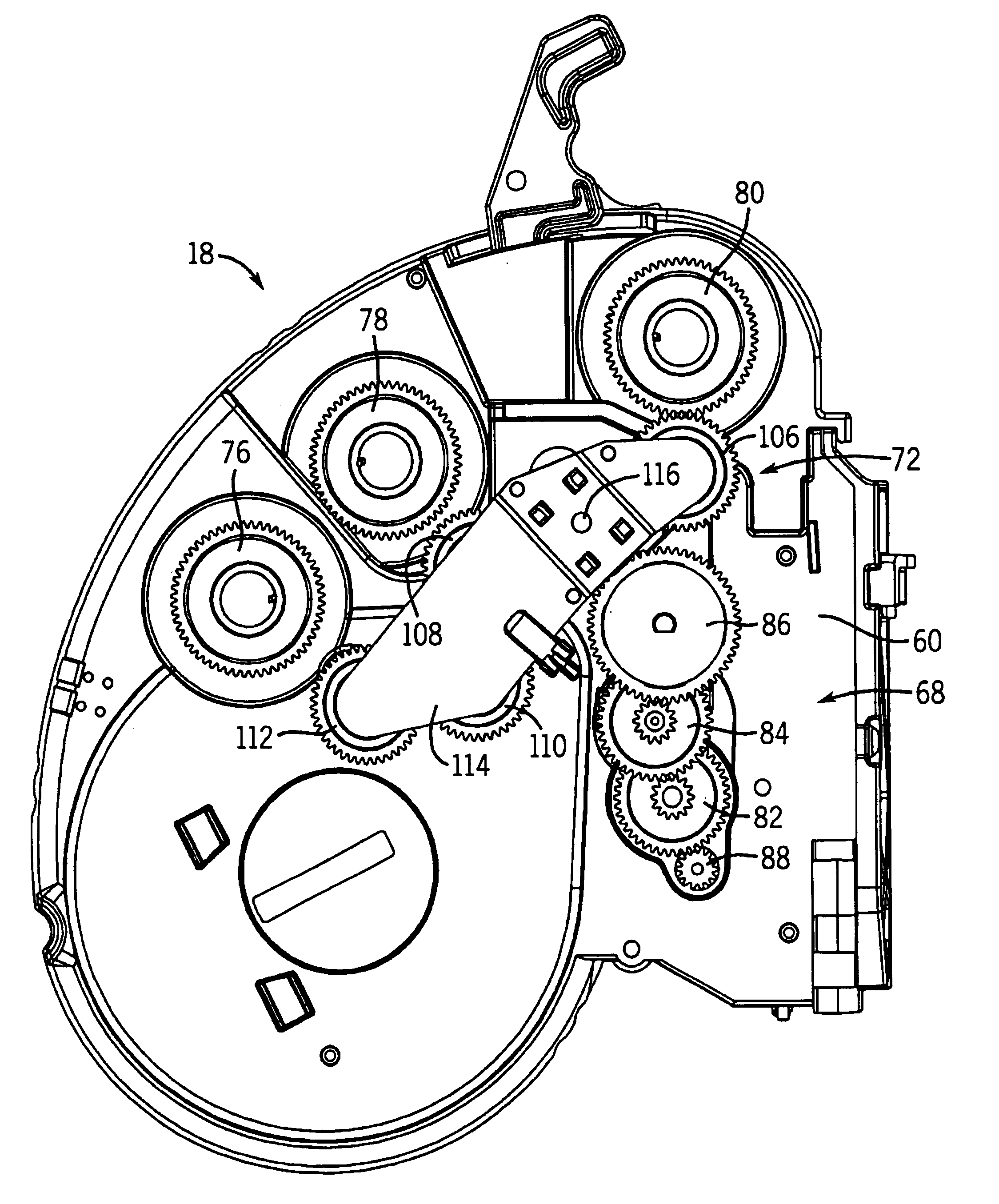
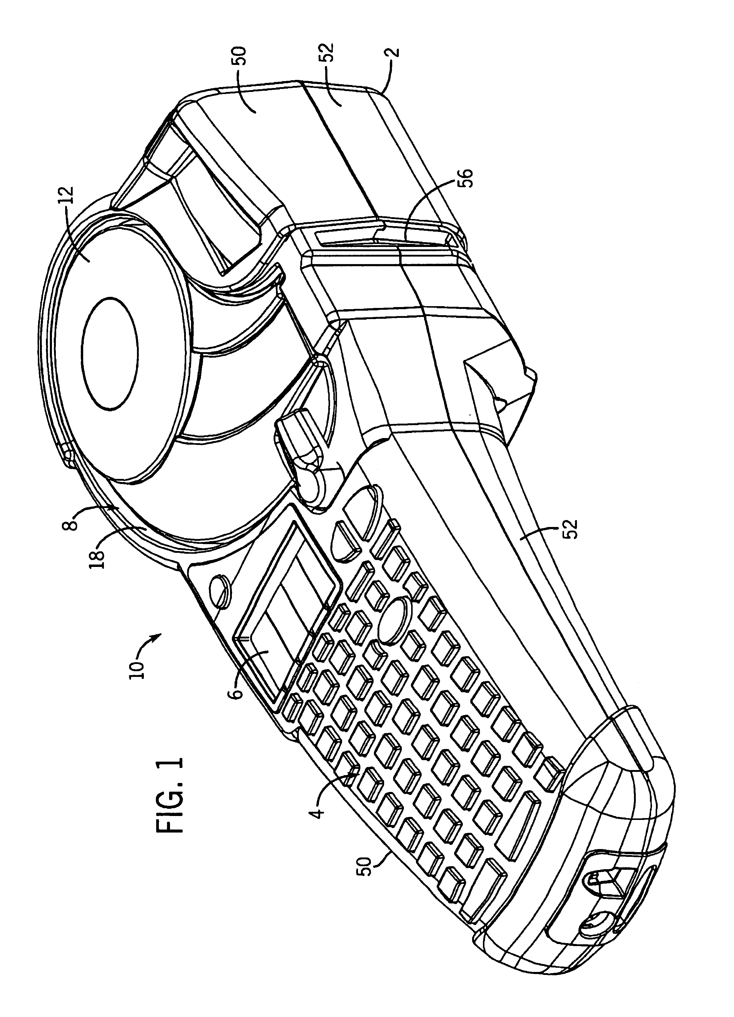
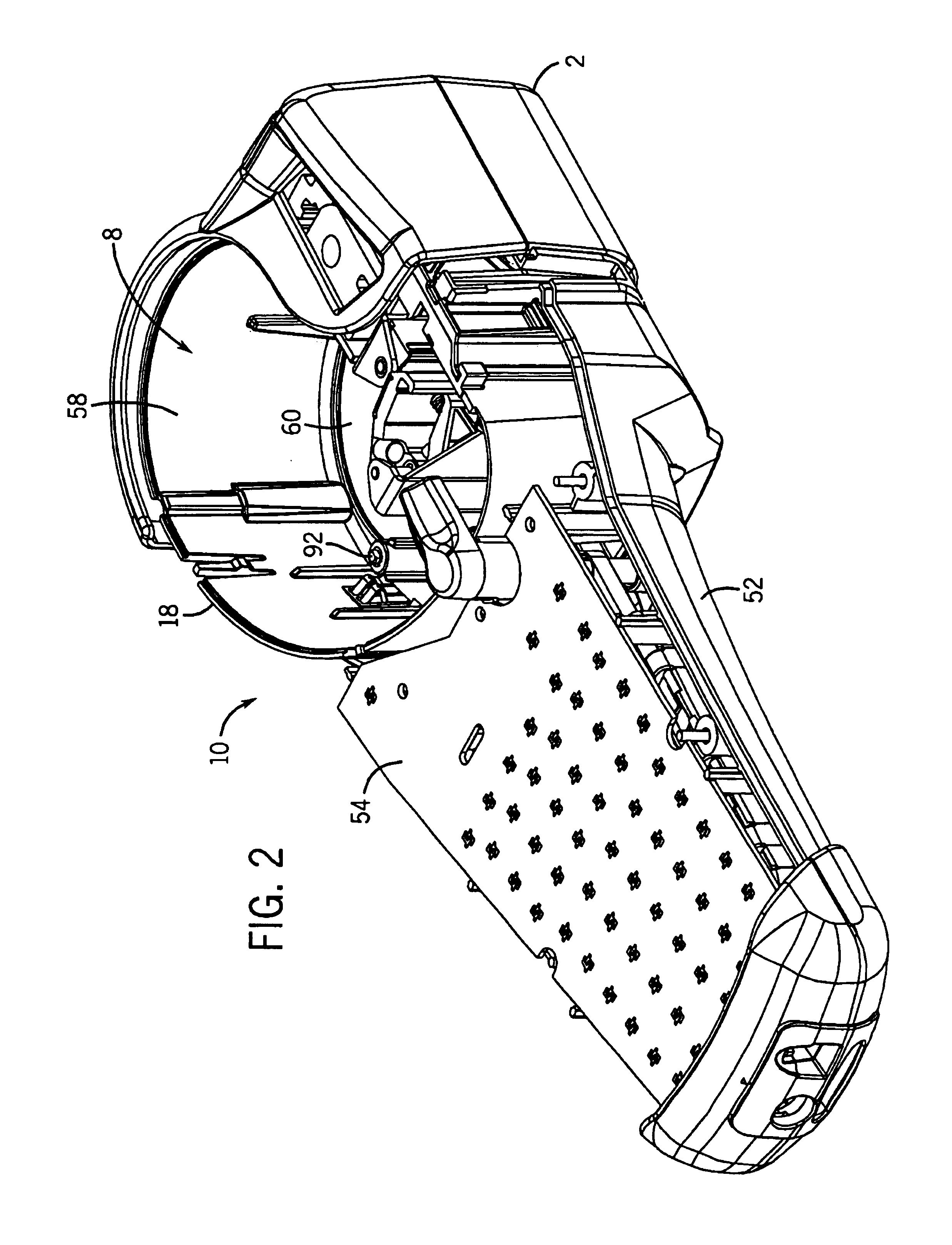
[0026]Referring particularly to FIGS. 1-7, a hand held thermal printer 10 employing a preferred embodiment of the present invention includes a molded plastic housing 2 that supports a keyboard 4 on its front surface and a display 6 positioned above the keyboard 4. An opening 8 formed in the housing 2 above the display 6 receives a cartridge 12 containing label media 14 and an ink ribbon 16. The cartridge 12 is inserted through the opening 8 into a cartridge receptacle 18 housed in the printer housing 2, and the label media 14 and ink ribbon 16 from the cartridge 12 are threaded through a printer mechanism assembly 20 including a print head 22 and a platen roller 24 for printing indicia on labels forming part of the label media 14. The printed labels pass through a cutter mechanism 26 which cuts the label media 14 to separate the printed labels from unprinted labels.

[0027]The label media 14 is known in the art, and generally comprises a carrier web which supports a series of adhesive...


PUM


Abstract

A printer, suitable for use in a hand held printer, having a dual direction drive mechanism for driving ink ribbon in a forward feed direction and a reverse feed direction. The drive mechanism is mounted in a printer body, and includes a stationary gear drive assembly engageable with a pivotal drive gear assembly having a forward feed position and a reverse feed direction.

Description

CROSS REFERENCES TO RELATED APPLICATIONS[0001]Not ApplicableSTATEMENT REGARDING FEDERALLY SPONSORED RESEARCH[0002]Not ApplicableTECHNICAL FIELD[0003]The present invention relates to a thermal transfer printer, and more particularly to a printer having a dual direction drive mechanism for driving ink ribbon and / or label media in a forward feed direction and a reverse feed direction.DESCRIPTION OF THE BACKGROUND ART[0004]There are a number of U.S. patents that disclose electronic apparatus for printing indicia on labels, some of these are restricted to hand held units and others that disclose tabletop units. Hand held label printers, such as disclosed in U.S. Pat. No. 6,113,293, and tabletop printers, such as disclosed in U.S. Pat. Nos. 6,266,075 and 5,078,523, include the same general combination of elements, a print head, means for feeding label media to be printed past the print head, a microprocessor, a read only memory programmed with appropriate instructions to operate the micro...

Claims


Application Information

Patent Timeline
Patent Type & Authority Patents(United States)
IPC IPC(8): B41J33/44B41J3/407
CPCB41J33/44B41J3/4075
Inventor CARRIERE, RICHARD L.WILKEN, KEVIN L.
Owner BRADY WORLDWIDE INC
Why Eureka
Try Eureka