Digital filter for NMR an MRI applications

a technology of digital filter and mri, applied in the field of digital filter for nmr an mri application, can solve the problems of loss of information which is very small for high-resolution nmr spectroscopy, distortion of nmr spectrum, and linear-phased fir filter in nmr and mri is the shape of nmr signal in time domain,

Active Publication Date: 2006-07-04
BRUKER SWITZERLAND AG
View PDF6 Cites 4 Cited by
  • Summary
  • Abstract
  • Description
  • Claims
  • Application Information

AI Technical Summary

Problems solved by technology

The most important disadvantage of the application of linear-phased FIR filters in NMR and MRI is the shape of the NMR signal in the time domain at the output of the filter.
If only the Portion B2 without the portion [B2] of the decaying oscillations is cut-off, this would lead to distortions in the NMR spectrum.
The fact that signal portions are cut off with this method results in the loss of some information which is very small for high-resolution NMR spectroscopy, since usually TBA.
The cut-off process itself can produce abrupt signal decay at the end of the filtered NMR signal, so that base line distortions in the NMR spectrum are produced if no counter-measures are taken.
The digital NMR signal F′ at the output of the digital filter usually contains undesired disturbing components which are caused by the quality of the receiver electronics used.
This function, however, is not appropriate for compensating the DC component of F′ since the rising and decaying oscillations of F′ would still remain uncompensated and cause distortions in the NMR spectrum.
Cutting off the very weak rising and decaying oscillations nevertheless represents a small loss in information which may still noticeably deteriorate the quality of the MRI images.
This calculation process RV has the following disadvantages:1. The group delay time of the digital filter cannot be freely selected but must be adjusted to the existing NMR or echo signal.
Although this is almost general practice anyway, it still limits the possibilities.6. In MRI, the rising and decaying oscillations B1 and B2 must be cut off.
Information is nevertheless lost thereby possibly deteriorating the sharpness of the sectional images.

Method used


Image

  • Digital filter for NMR an MRI applications
  • Digital filter for NMR an MRI applications
  • Digital filter for NMR an MRI applications

Examples


Embodiment Construction

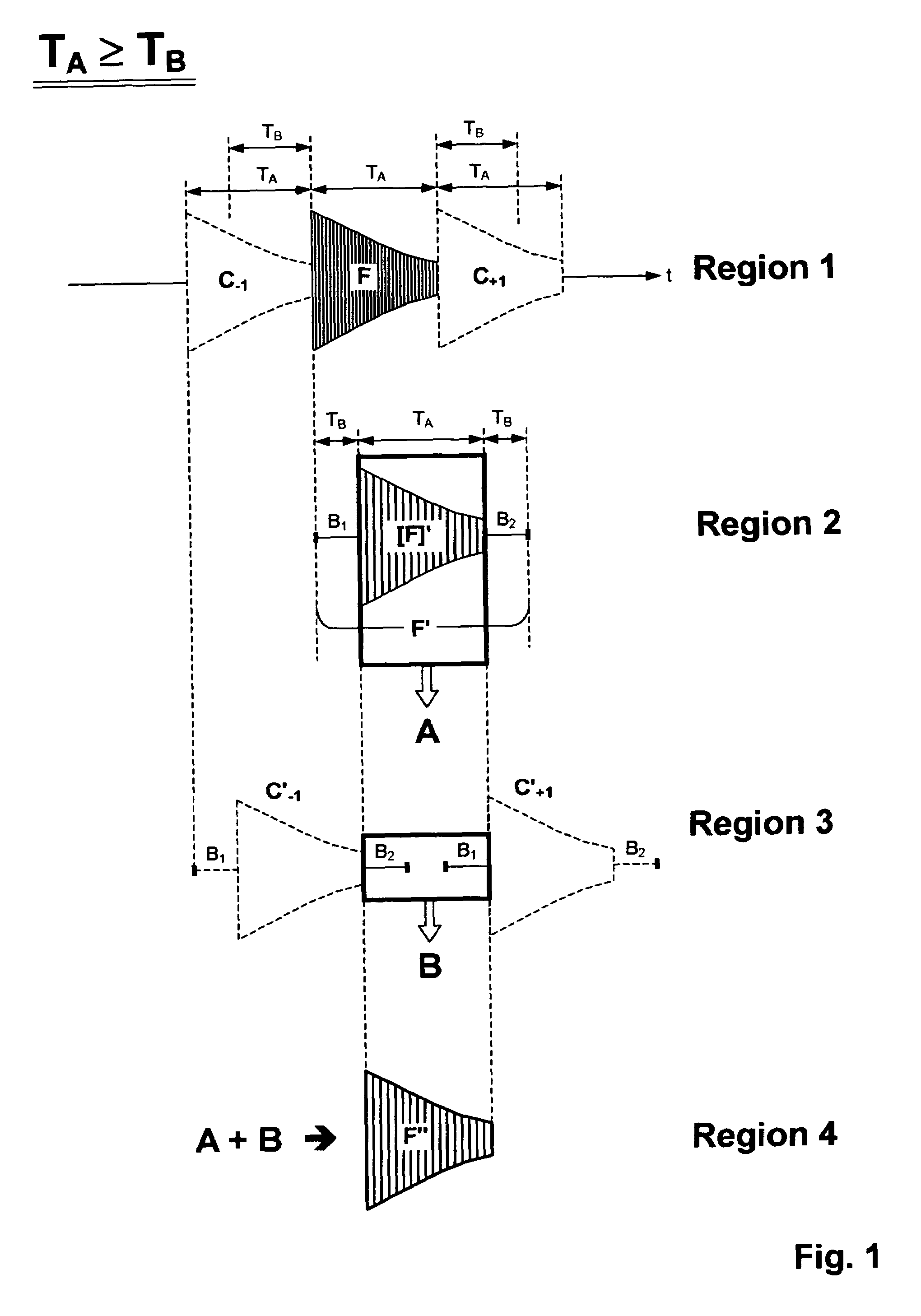
[0065]FIG. 1 shows the case of TA≧TB and one can see that three sequential signals F′, namely C′−1, F′ and C′+1 are completely sufficient to define F″ (see regions 2 and 3). C′−1 and C′+1 are copies of F′ and are each displaced about TA in a positive and negative direction with respect to F′. Further copies of F′ are not required since they are sufficiently far away from F′ that their rising or decaying oscillations can no longer overlap the signal F′. In this case N=1.

[0066]FIG. 1 shows initial selection of the NMR signal [F]′ only and its storage as value A (region 2). The decaying oscillation B2 of C′−1 and the rising oscillation B1 of C′+1 are subsequently selected and stored as value B (region 3). A and B are finally added which produces the desired signal F″ of length TA (region 4).

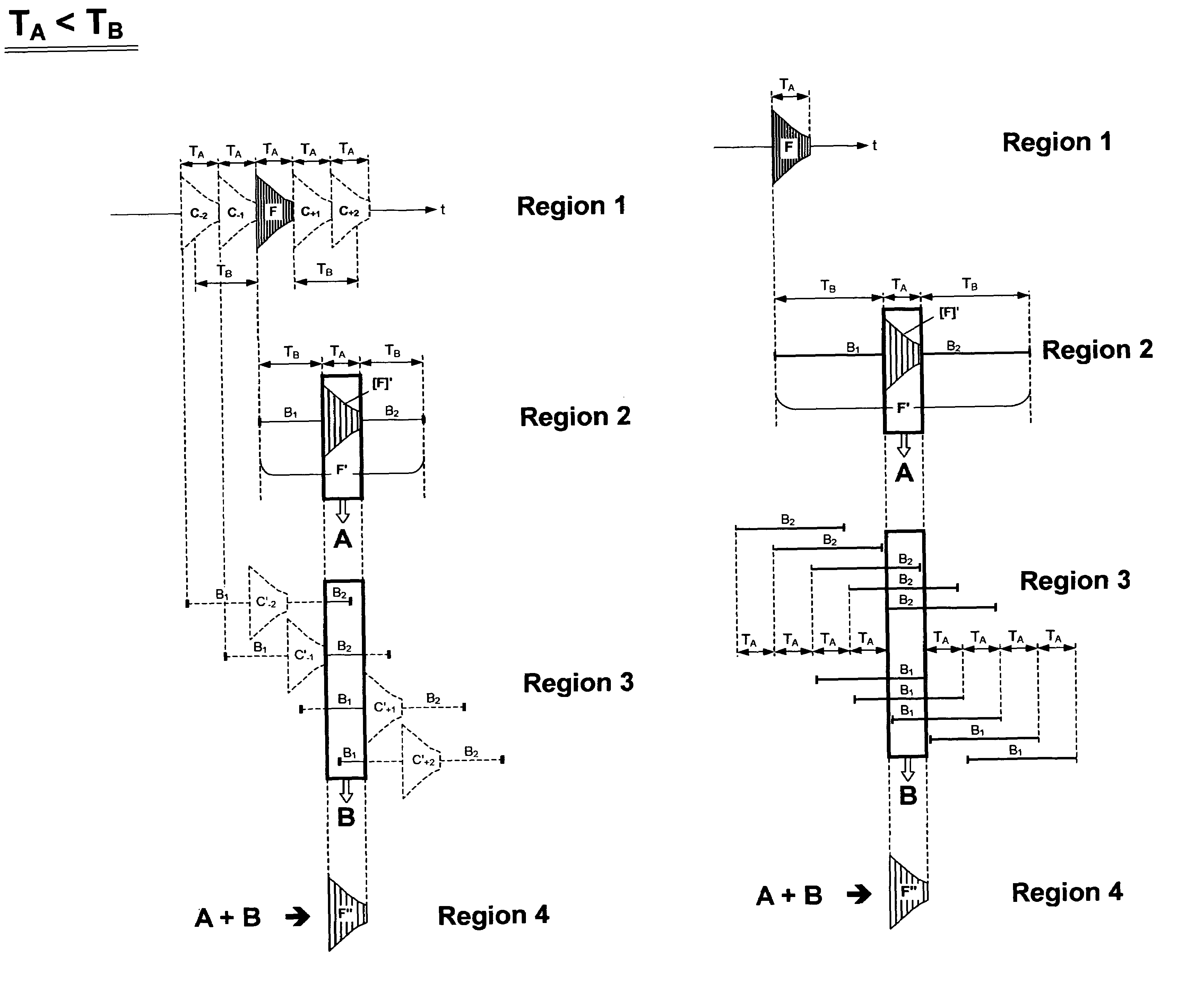
[0067]If TAB more than three successive signals F′ must be taken into consideration. FIG. 3 shows a corresponding example, wherein TB=1.33 TA and five successive signals F′ are required to define F″...


PUM


Abstract

A method for operating a magnetic resonance spectrometer with a digital filter whose input is fed with an NMR signal of a time length TA, and whose output signal consists of a rising oscillation B1 of a length TB, a signal portion [F]′ which consists of a filtered FID or echo signal of the length TA and a decaying oscillation B2 of a length TB, wherein this output signal is initially modified using a calculation process RV, and is subsequently transformed by Fourier transformation to a desired NMR spectrum, is characterized in that, during the calculation process RV, only the signal portion [F]′ is initially selected, at least N copies of the rising oscillation B1 are subsequently generated in positive time shifts TA with respect to each other and are positioned on the signal portion [F′] in time such that the end of the first rising oscillation is positioned at the end of the signal portion, at least N copies of the decaying oscillation B2 are generated in negative shifts TA and are positioned on the signal portion [F′] in time such that the start of the first decaying oscillation is positioned at the start of the signal portion [F′], and all N copies of the rising oscillation B1 defined in this manner and N copies of the decaying oscillation B2 defined in this manner are added to the signal portion [F′], and only the range TA thereof which contains the signal portion [F′] is selected as resulting signal F″ of the calculation process RV, wherein the number N is to be calculated using the formula N=TB / TA and rounded to the next higher integer number. This exactly compensates for the influence of the group delay time of digital, linear-phased filters in a mathematically exact manner.

Description

[0001]This application claims Paris Convention priority of DE 10 2004 017 667.1 filed Apr. 10, 2004 the complete disclosure of which is hereby incorporated by reference.BACKGROUND OF THE INVENTION[0002]Digital filters have been used for a relatively long time for receiver systems in modern NMR and MRI spectrometers. They are generally designed as low-pass filters, and are applied together with the over-sampling and decimation methods. Since the receiver system usually contains a quadrature detector, two digital filters are required for each receiver system.[0003]FIG. 6 shows the last function blocks of a modern NMR receiver system with two quadrature channels A and B including the two digital filters 3a and 3b, and also the two digitizers 2a and 2b for digitizing the two analog NMR signals of the channels A and B.[0004]The sampling rate of the digitizers is normally chosen as large as possible to be more flexible in the design of the analog anti-aliasing filters and to profit from t...

Claims


Application Information

Patent Timeline
Patent Type & Authority Patents(United States)
IPC IPC(8): G01V3/00A61B5/055G01R33/36G01R33/46
CPCG01R33/4625
Inventor LENDI, PIETROTSCHOPP, WERNER
Owner BRUKER SWITZERLAND AG
Why Eureka
Try Eureka