Communication cable

a technology of communication cable and interposer, which is applied in the direction of power cables, cables, insulated conductors, etc., can solve the problems of increasing difficult to insert into the modular, and the interposer cannot be easily flattened, so as to reduce the amount of attenuation, reduce the difference in delay time, and reduce the cross talk

Inactive Publication Date: 2001-10-09
FURUKAWA ELECTRIC CO LTD
View PDF4 Cites 123 Cited by
  • Summary
  • Abstract
  • Description
  • Claims
  • Application Information

AI Technical Summary

Benefits of technology

By inserting the central interposer 2 having the cross sectional area S1 defined above, space between the four twisted wire pairs increases and it is possible to decrease the cross talk even when the difference in the pitch is decreased in order to decrease the difference in delay time between the twisted wire pairs.
The inter-pair interposer 6, that fill the clearance created when the four twisted wire pairs are entwined, is made...

Problems solved by technology

However, this increases the difference in delay time and therefore the two items of target characteristics cannot be satisfied with only this technique.
However, it is difficult to insert the cable covered by the sheath 3, while keeping the cable f...

Method used


Image

  • Communication cable
  • Communication cable
  • Communication cable

Examples


embodiment 1

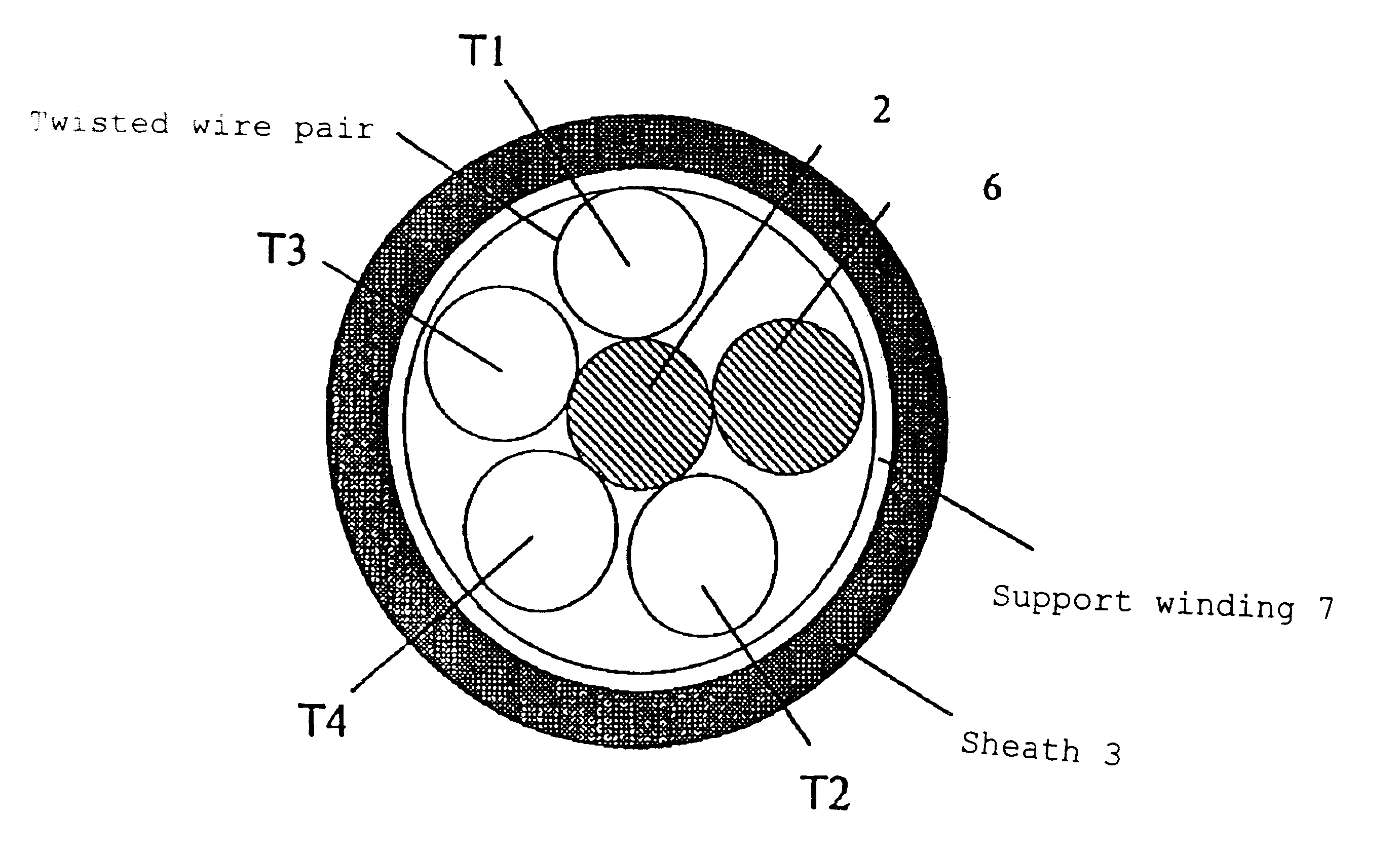
The first embodiment is a case where four twisted wire pairs T1, T2, T3, T4 and the inter-pair interposer 6 made of PE in a 1.4 mm thread are entwined around the central interposer 2 made of polyolefin in a round rod of a diameter of 1.4 mm, as shown in FIG. 10. Twist pitches of the four twisted wire pairs T1, T2, T3, T4 are set to 9.9 mm (T1), 10.9 mm (T2), 14.4 mm (T3) and 23.8 mm (T4), (refer to Table 1)

At this time, the inter-pair interposer 6 made of PE thread was inserted between the twisted wire pair T1 having the least pitch and the twisted wire pair T2, and was entwined to adjoin T1.

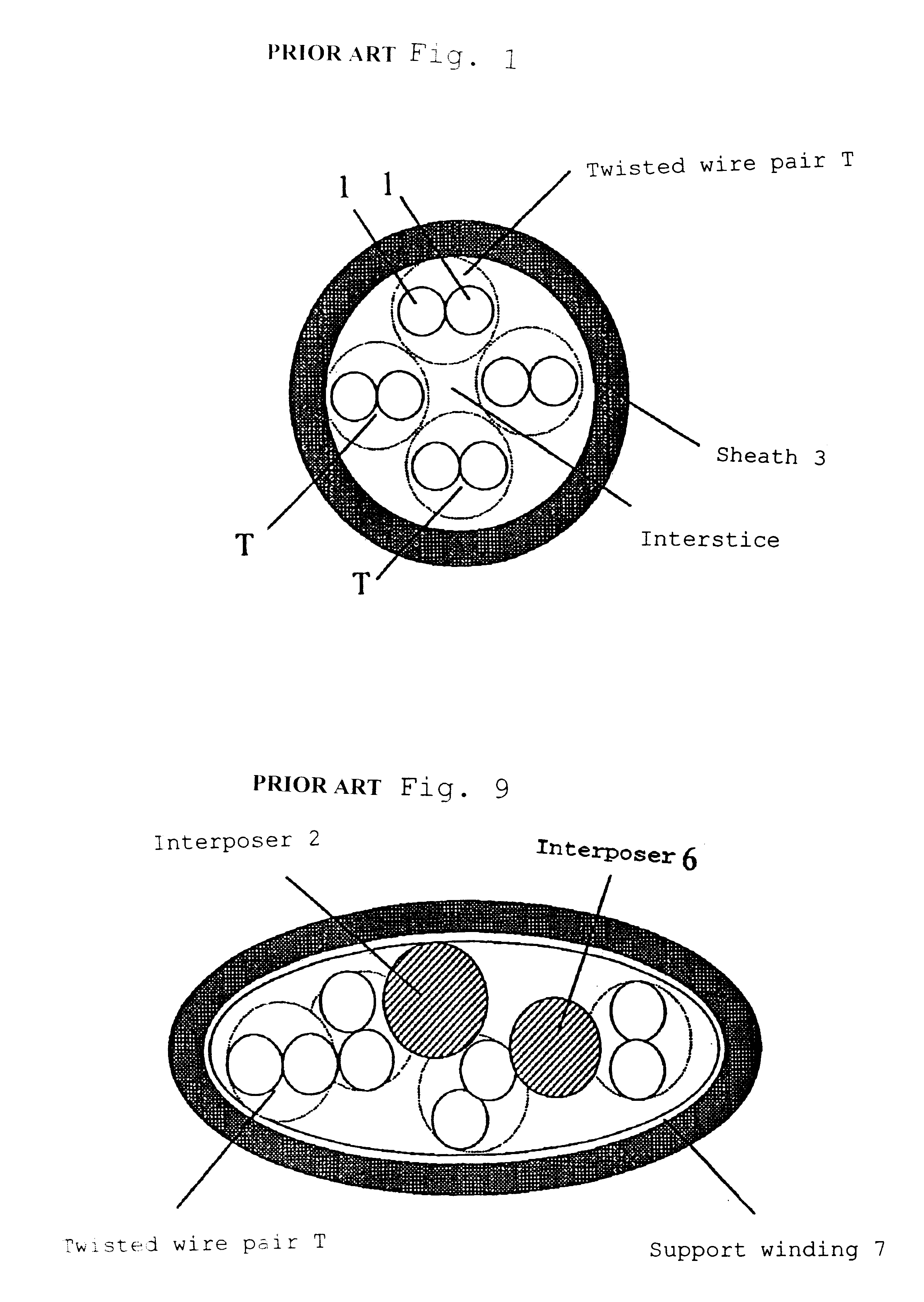
A cable was made as a comparative example by using a central interposer 2 having diameter of 0.8 mm and entwining the twisted wire pairs having similar pitches as shown in FIG. 11. FIG. 12 and FIG. 13 show the measured values of near-end cross talk of the first embodiment and the comparative example, respectively. Each graph is a plot of the near-end cross talk measured on all (six) selected com...

embodiment 2

The second embodiment is a case where four twisted wire pairs T1, T2, T3, T4 and the inter-pair interposer 6 made of a rod-shaped body made of polyolefin in and 1.4 mm in diameter are entwined around the central interposer 2 made in a rod-shaped body made of polyolefin in having a diameter of 1.6 mm, as shown in FIG. 14.

embodiment 3

The third embodiment is a case where the four twisted wire pairs T1, T2, T3, T4 and the inter-pair interposer 6 made of a rod-shaped body made of polyolefin and 1.2 mm in diameter are entwined around the central interposer 2 made in a rod-shaped body made of polyolefin in having a diameter of 1.8 mm, as shown in FIG. 15. It was confirmed that these two embodiments have effects similar to those of the first embodiment.

Embodiment 4

The fourth embodiment is a case where one central interposer 2 made of PP yarn 11000d (cross sectional area 1.02 mm.sup.2 or larger) is provided to fill the central interstice instead of a rod-like interposer, and one inter-pair interposer 6 made of PP yarn 11000d and four twisted wire pairs are entwined around thereof as shown in FIG. 16. A similar effect were confirmed also in this embodiment.

In any of the first through fourth embodiments, a support winding layer 7 was formed by taping around the four twisted wire pairs and the rod made of a thermoplastic ...


PUM


Abstract

A communication cable is provided that satisfies the requirement of Cat.6 for near-end cross talk wherein the difference between the maximum and minimum values of delay time among the four twisted wire pairs constituting the cable is within 25 ns/100 m. The communication cable is made by entwining four twisted wire pairs (T1), (T2), (T3), (T4) made by twisting pairs of insulated wires made by covering electrically conductive wires by polyolefin thermoplastic resin with each pair being twisted with a twist pitch different from the others (pitch: P1<P2<P3<P4) and the inter-pair interposer (6) made of polyolefin thermoplastic resin, while being entwined with each wire pair, around a central interposer (2) made of polyolefin thermoplastic resin having cross sectional area of S1. Cross sectional area S1 of the central interposer (2) satisfies the relationship of inequality S1>=[{4.1 d/(1+{square root over (2)})}.0.35]2xpi, while the inter-pair interposer (6) that is entwined with the twisted wire pairs is located at such a position as adjoins the twisted wire pair (T1) having the least pitch P1 and does not adjoin the twisted wire pair (T4) having the largest pitch P4.

Description

The present invention relates to communication cables of a balanced type used for high-speed transmission in LAN's.A 4-pair cable called a category 5 cable is generally used for high-speed LAN systems with transmission signal speeds up to 100 Mbps. Specification standards for characteristic impedance, near-end cross talk and attenuation of this cable are specified in ISO / IEC and EIA / TIA, so that performance is ensured by conformity to the standard.Accordingly, conformity to the standard is achieved by differentiating the twist pitches of four twisted wire pairs (T, T, T, T) as shown in FIG. 1, with the difference between the twist pitches being made as large as possible. Each twisted wire pair T is made by twisting a pair of insulated wires 1 each consisting of an electrically conductive wire such as soft copper wire covered by polyolefin thermoplastic resin.A communication cable is made in a configuration such that a interposer 2 is disposed at the center of the entwined twisted wi...

Claims


Application Information

Patent Timeline
IPC IPC(8): H01B11/02H01B11/04H01B7/18
CPCH01B7/1895H01B11/04
Inventor HORIE, YASUSHICHIBA, KAZUOSAITO, MINORU
Owner FURUKAWA ELECTRIC CO LTD
Why Eureka
Try Eureka