Control circuit associated with saturable inductor operated as synchronous rectifier forward power converter

a control circuit and synchronous rectifier technology, applied in the direction of dc-dc conversion, dc-dc conversion, and conversion with intermediate conversion to dc, etc., can solve the problems of reducing power efficiency under light load conditions, cross conduction, and loss of conductan

Active Publication Date: 2007-02-06
SEMICON COMPONENTS IND LLC
View PDF6 Cites 116 Cited by
  • Summary
  • Abstract
  • Description
  • Claims
  • Application Information

AI Technical Summary

Benefits of technology

[0007]A circuit for synchronous rectifying of a power converter includes a transformer having a primary winding and a secondary winding. The secondary winding includes a first terminal and a second terminal. A switching voltage is produced across the second terminal and the first terminal of the secondary winding of the transformer as the transformer is being switched. A saturable inductor is coupled from the second terminal of the secondary winding of the transformer to a third terminal. A first transistor is coupled from the first terminal of the secondary winding of the transformer to a ground terminal. Furthermore, a second transistor is coupled from the third terminal to the ground terminal. The first and second transistors operate as synchronous rectifiers. An inductor is coupled from the

Problems solved by technology

However, a forward voltage drop across the rectifying diode inevitably causes a conduction loss and renders the rectifying diode as the key component for producing the loss.
However, the drawback of the aforementioned conventional synchronous rectif

Method used


Image

  • Control circuit associated with saturable inductor operated as synchronous rectifier forward power converter
  • Control circuit associated with saturable inductor operated as synchronous rectifier forward power converter
  • Control circuit associated with saturable inductor operated as synchronous rectifier forward power converter

Examples


Embodiment Construction

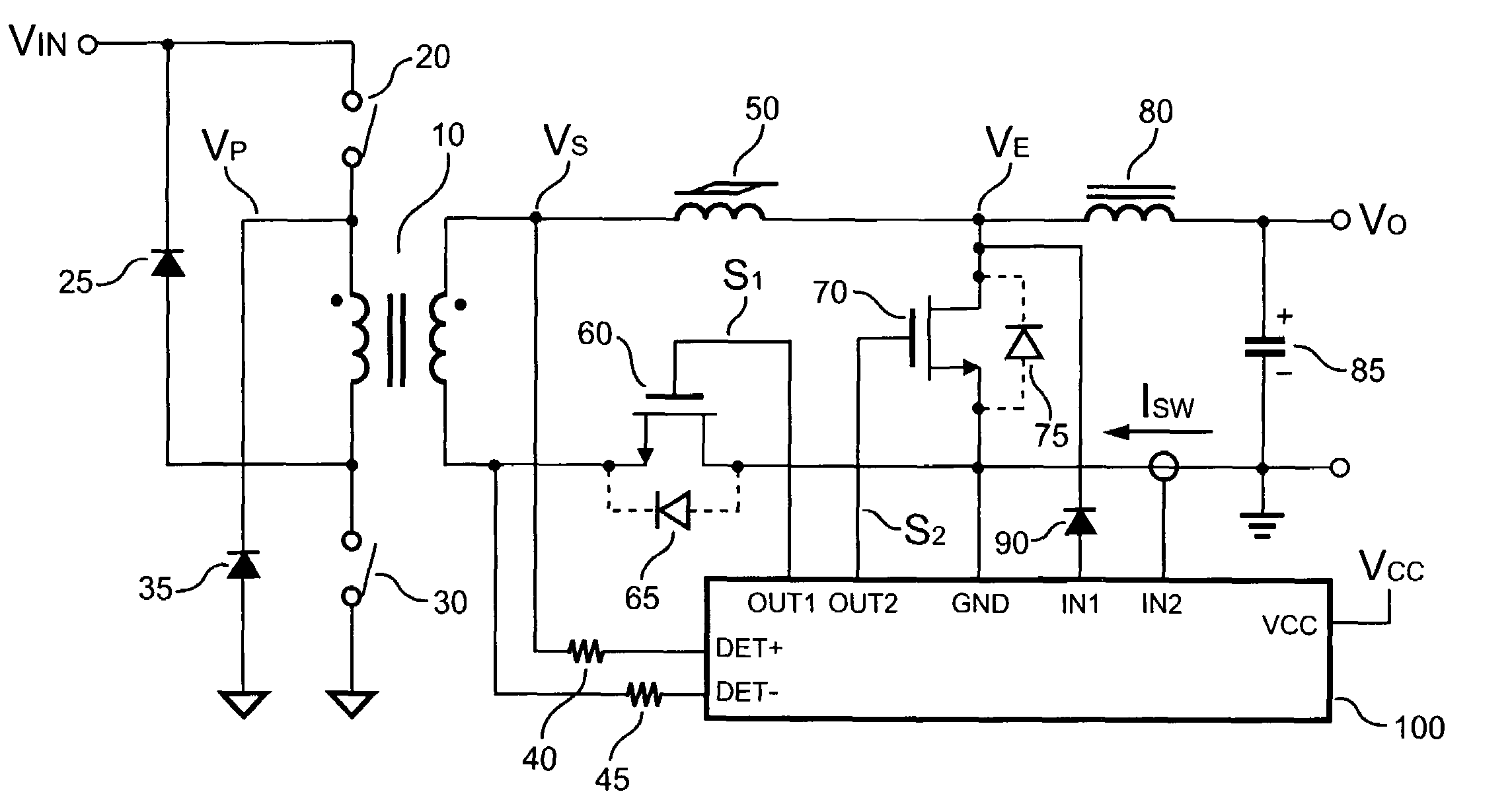
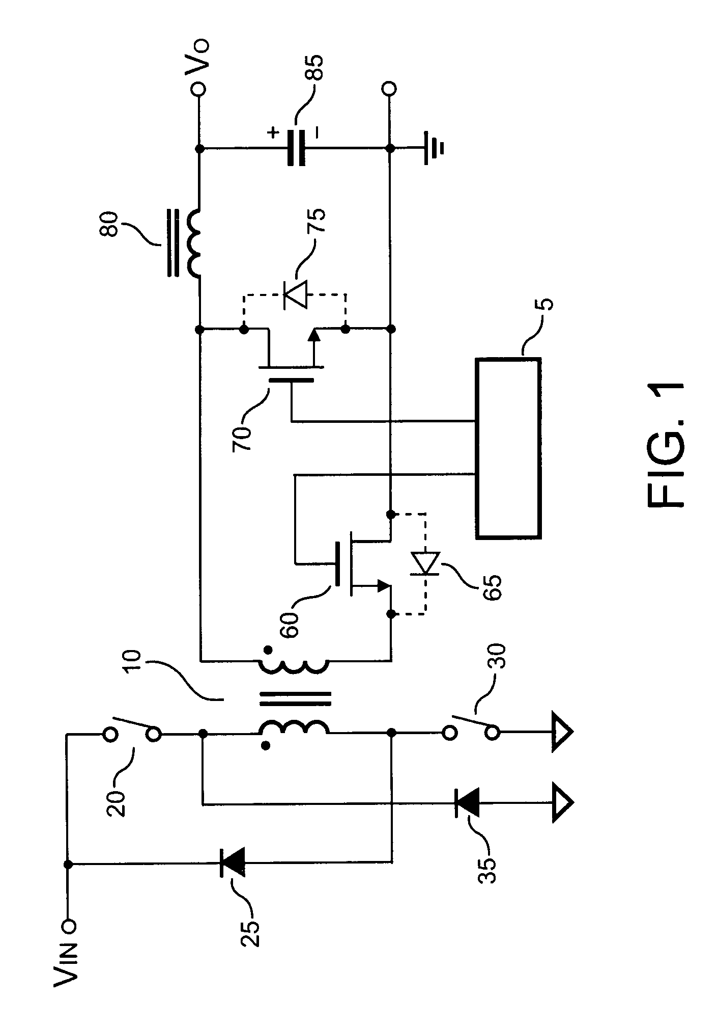
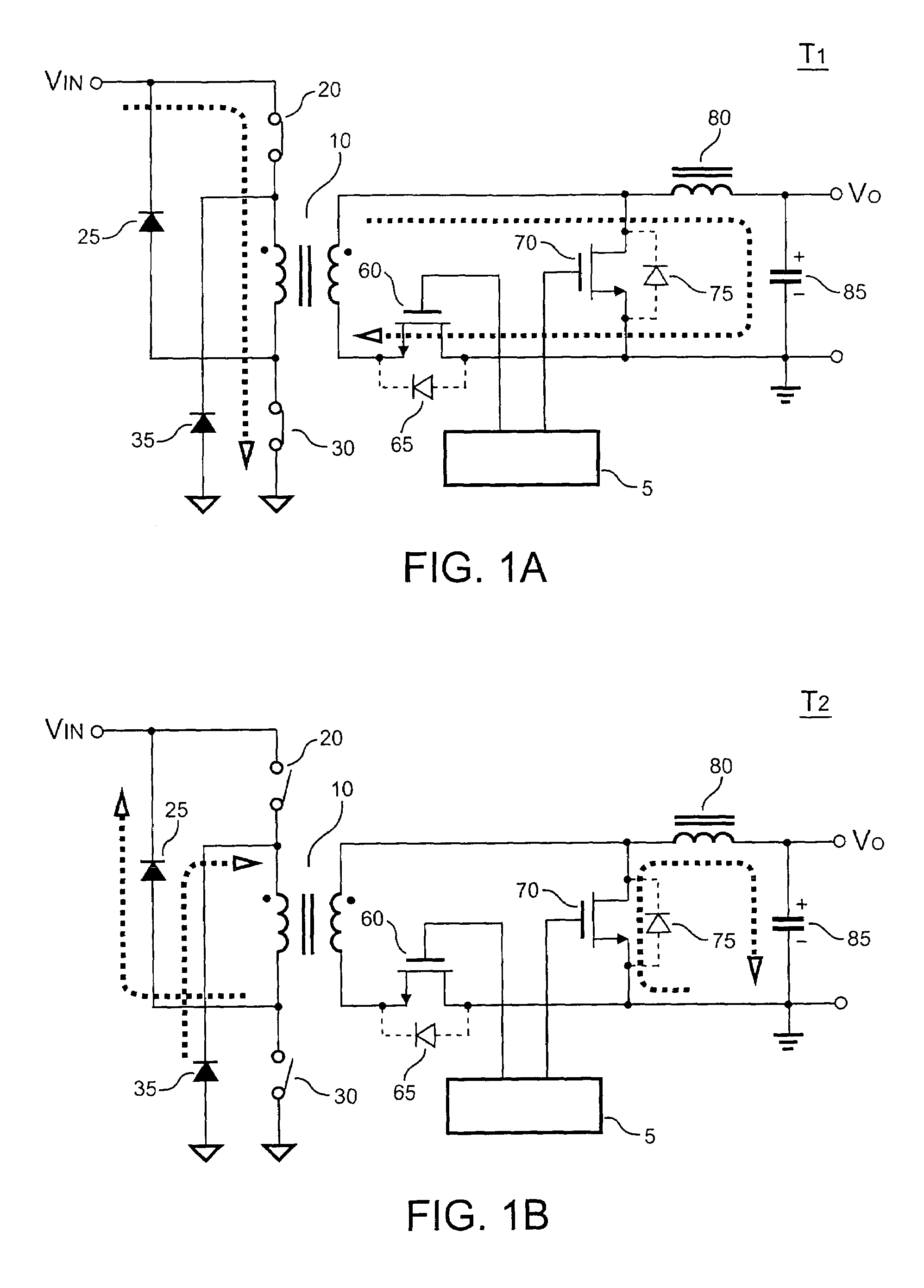
[0021]FIG. 3 illustrates a circuit of synchronous rectifying according to a first embodiment of the present invention. The aforementioned circuit includes a transformer 10 having a primary winding and a secondary winding. The secondary winding includes a first terminal and a second terminal. A switching voltage VS is produced across the second terminal and the first terminal of the secondary winding in response to the switching of the transformer 10. A saturable inductor 50 is connected from the second terminal of the secondary winding to a third terminal. A transistor 60 is connected from the first terminal of the secondary winding to a ground terminal. A transistor 70 is connected from the third terminal to the ground terminal. An inductor 80 is connected from the third terminal to an output terminal of the power converter to generate an output voltage VO. A current-sensing apparatus generates a current signal in response to the inductor current ISW. A control circuit 100 is utili...


PUM


Abstract

A circuit for synchronous rectifying is provided for forward power converter. A secondary winding of a transformer includes a first terminal and a second terminal for generating a switching voltage. A saturable inductor is coupled from the second terminal to a third terminal for providing a delay time. A first transistor is coupled from the first terminal to a ground terminal. A second transistor is connected from the third terminal to the ground terminal. The first and second transistors operate as synchronous rectifiers. An inductor is equipped from the third terminal to an output terminal of the forward power converter. Furthermore, a current-sensing device generates a current signal in response to an inductor current of the inductor. A control circuit receives the switching voltage and the current signal for generating a plurality of signals for driving a plurality of transistors, respectively.

Description

BACKGROUND OF THE INVENTION[0001]1. Filed of the Invention[0002]The present invention relates to a control circuit of forward power converter, and more particularly, to a synchronous rectifier control circuit for a forward power converter for improving efficiency of power conversion.[0003]2. Description of the Related Art[0004]Power converters have been frequently used for converting an unregulated power source to a constant voltage source and / or a constant current source. A transformer having a primary winding and a secondary winding is typically used for power conversion. In a typical application, the primary winding is coupled to an unregulated power source, preferably a DC voltage source, and a switching device is connected to the primary winding for switching on and off the conduction between the power source and the primary winding. A rectifying diode is typically connected to the secondary winding for rectifying the energy converted from the primary winding into a DC voltage....

Claims


Application Information

Patent Timeline
IPC IPC(8): H02M7/217
CPCH02M1/16H02M3/33592H02M3/3353Y02B70/1475Y02B70/10
Inventor YANG, TA-YUNG
Owner SEMICON COMPONENTS IND LLC
Why Eureka
Try Eureka