Magnetic device

a magnetic device and magnet technology, applied in the direction of magnets, magnet bodies, instruments, etc., can solve the problems of damage to the magnetic device, the magnetic attraction between the contained magnet and the outer steel surface might not be reliably guaranteed, and the magnet does not necessarily easily turn 90 degrees to face the normally-extending surface of the container, etc., to achieve the effect of improving the magnetic attraction

Inactive Publication Date: 2006-07-04
HIROMORI CORP
View PDF6 Cites 3 Cited by
  • Summary
  • Abstract
  • Description
  • Claims
  • Application Information

AI Technical Summary

Benefits of technology

[0005]Accordingly, it is an object of the present invention to improve magnetic attraction between two surfaces.
[0006]It is also an object of the present invention to improve reliability of magnetic attraction between two surfaces.
[0007]It is another an object of the present invention to facilitate retention and positioning of a device against an outer surface, e.g., by magnetic attraction, and improve reliability of such retention.
[0008]It is a further object of the present invention to facilitate retention of various articles between two surfaces, e.g., by positioning these articles in a magnetic force field.
[0009]It is still another object of the present invention reduce danger of damage to a magnetic device by properly orienting at least one magnet within the same to ensure proper magnetic attraction without shaking the device.

Problems solved by technology

However, it has been found where a magnet is, e.g., substantially in the shape of a disk and resting against one interior surface of the container, the magnet does not necessarily easily turn 90 degrees to face a normally-extending surface of the container that is brought against an outer magnetic / magnetizable surface such as a steel surface.
Accordingly, magnetic attraction between the contained magnet and outer steel surface might not be reliably ensured, with it being necessary for a user to shake the device to properly orient the magnet therein (such shaking could easily damage the magnetic device).
This 90 degree turning of a disk-shaped magnet is especially problematic the closer in shape to a cylinder or spindle the main body of the device containing the magnet.

Method used


Image

  • Magnetic device
  • Magnetic device
  • Magnetic device

Examples


Embodiment Construction

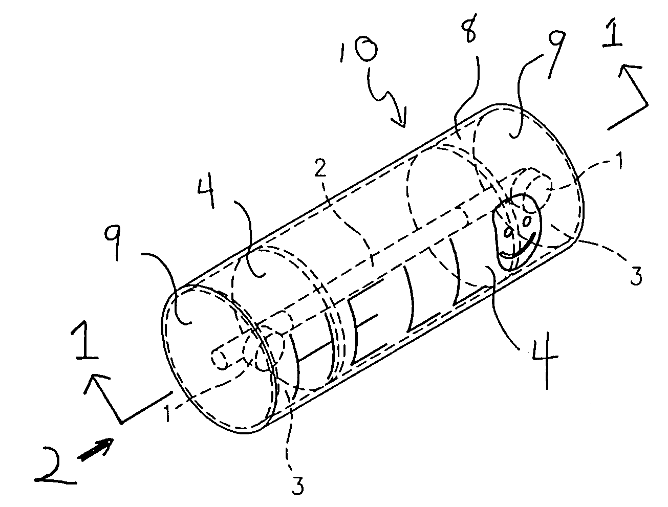
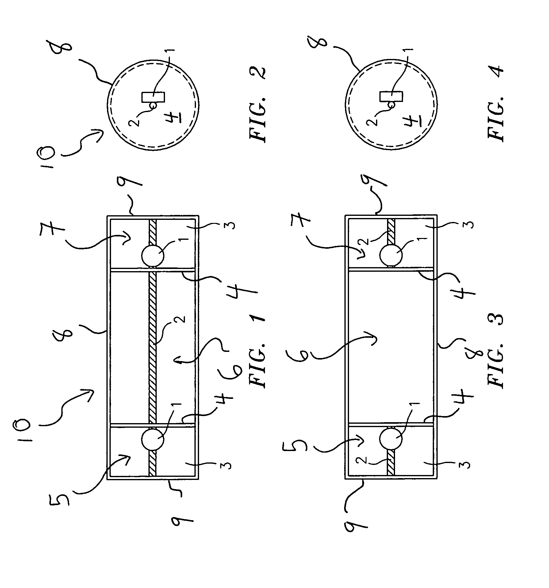
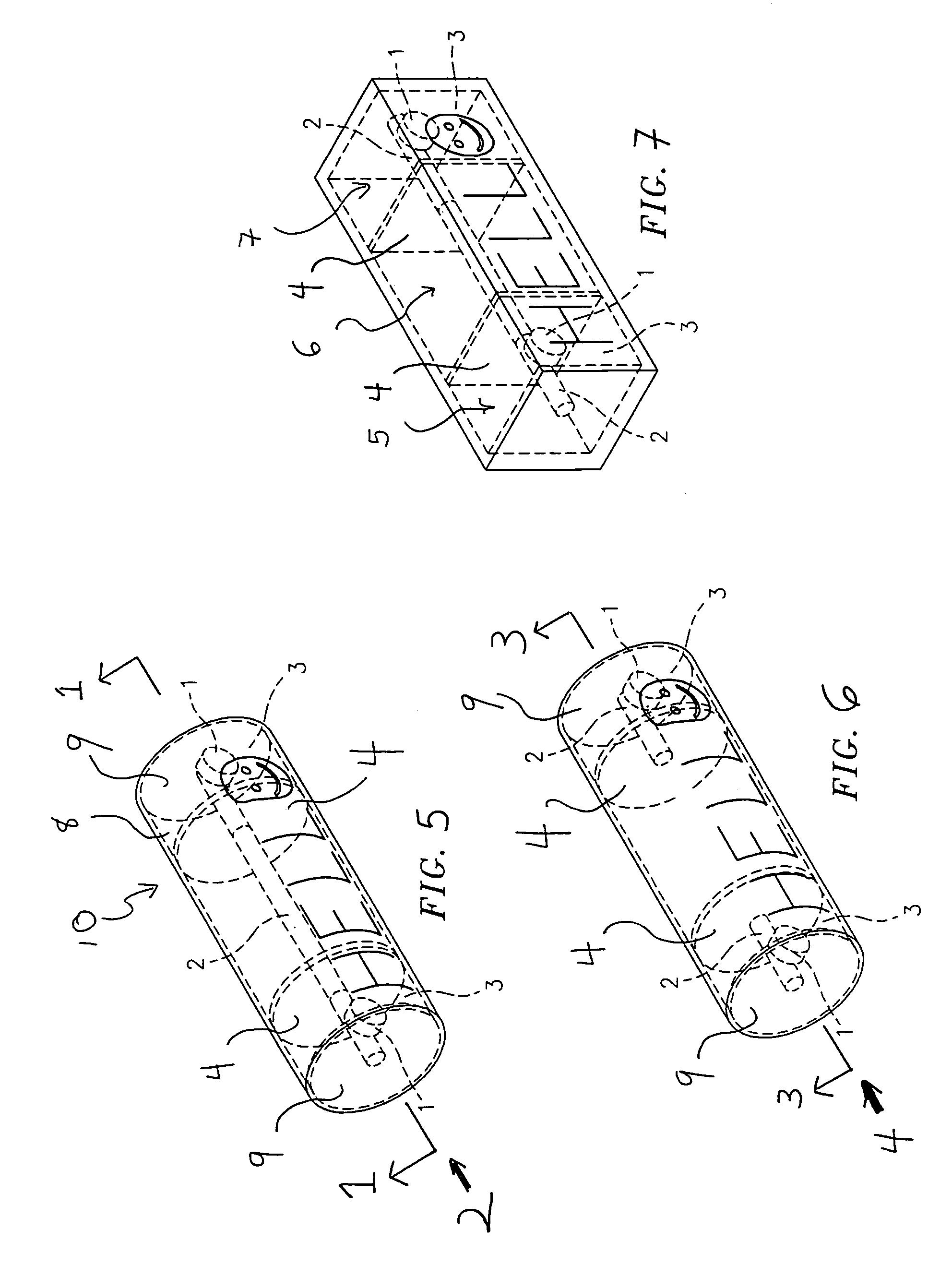
[0020]Referring the present invention in which similar components have been denoted by the same reference numerals, FIGS. 1, 2 and 5 illustrate one embodiment of the device 10 substantially in the shape of a hollow spindle or cylinder and constructed, e.g., from transparent plastic. Decorative lettering and / or patterning can appear upon the outer surface of the spindle or cylinder, e.g., along the curved, longitudinally-extending surface 8 as illustrated. Partitions 4 respectively divide the interior chambers 5, 6 and 7 from one another in the longitudinal direction, with disk-shaped magnets 1 being positioned in the two outer chambers 5 and 7 bordering the central chamber 6 in the longitudinal direction and which does not contain a magnet in the illustrated embodiment. Alternatively, a magnet can be easily positioned within this central chamber 6 within the context of the present invention.

[0021]A single rod 2 extends entirely across all three chambers 5–7 in the embodiment shown i...


PUM

PropertyMeasurementUnit
magneticaaaaaaaaaa
magnetizableaaaaaaaaaa
shapeaaaaaaaaaa

Abstract

An improved magnetic device is provided for adhering to an outer magnetic or magnetizable surface in a secure, reliable manner, by ensuring proper orientation of a magnet contained therein at all times.

Description

BACKGROUND OF THE PRESENT INVENTION[0001]The present invention is directed to an improved magnet device for adhering to a magnetic or magnetizable surface and retaining, e.g., articles such as paper between the device and surface, whereby reliability of magnetic attraction and ultimate retention against the surface is improved.[0002]Various devices for magnetically adhering to surfaces are known, e.g., magnets for adhering to refrigerators, etc. In this regard, structures containing permanent magnets are also known, e.g., U.S. Pat. No. 5,347,253 showing a block having a magnetic body therein and U.S. Pat. No. 4,741,534 showing a block having a metal ball therein which can be attracted to magnetic objects. Furthermore, U.S. application Ser. No. 10 / 642,312 filed Aug. 15, 2003, the contents of which are incorporated by reference herein, discloses various embodiments of devices containing permanent magnets and in various polygonal shapes, whereby the respective devices can adhere to an ...

Claims


Application Information

Patent Timeline
Patent Type & Authority Patents(United States)
IPC IPC(8): H01F7/02G03G15/08G09B1/08
CPCG09B1/08H01F7/0252H01F7/0221
Inventor HIROMORI, JUNJI
Owner HIROMORI CORP
Why Eureka
Try Eureka