
Portable modular wheel lift

a technology for modular vehicles and wheels, applied in the direction of lifting devices, inclined ship lifting, construction, etc., can solve the problems of unsafe situation, difficult use of ramp devices for lifting modified vehicles, etc., and achieve the effect of convenient stackability

Inactive Publication Date: 2006-07-11
BRANSTETTER ANN
View PDF7 Cites 26 Cited by
  • Summary
  • Abstract
  • Description
  • Claims
  • Application Information

AI Technical Summary

Benefits of technology

"The present invention provides a portable modular wheel lift for elevating the front and rear wheels of a vehicle with body portions extended to a height proximal to the ground. The lift includes a base lift unit and a primary ramp unit that can be aligned with the vehicle body portions and joined by pivoting. The primary ramp unit has a first ramp surface angled for gradual traversal by a vehicle wheel. The lift also includes additional lift units that can be stacked on the base lift unit to elevate the vehicle wheels to a second lift position. The lift allows for elevating one or more wheels without disrupting the vehicle body portions, and provides a platform for maintenance activities. The method of assembly and operation of the lift is also provided."

Problems solved by technology

Due to the height above the ground of prior portable ramp devices, each ramp device is difficult to use for lifting modified vehicles having ground clearance heights reduced to between about three inches to about six inches due to suspension modifications and / or addition of front and rear bumper assemblies extending low to the ground surface, as is typical of modified “low aspect” or “street rod” vehicles.
Further, this type of ramp device requires end-to-end alignment for proper cradling by the end brackets extended from each rear portion of each ramp segment, thereby posing an unsafe situation if the operator attempted to assemble the aligned ramp segments while a front or rear wheel is on a first ramp segment and is partially elevated above a ground surface.

Method used


Image

  • Portable modular wheel lift
  • Portable modular wheel lift
  • Portable modular wheel lift

Examples


Embodiment Construction

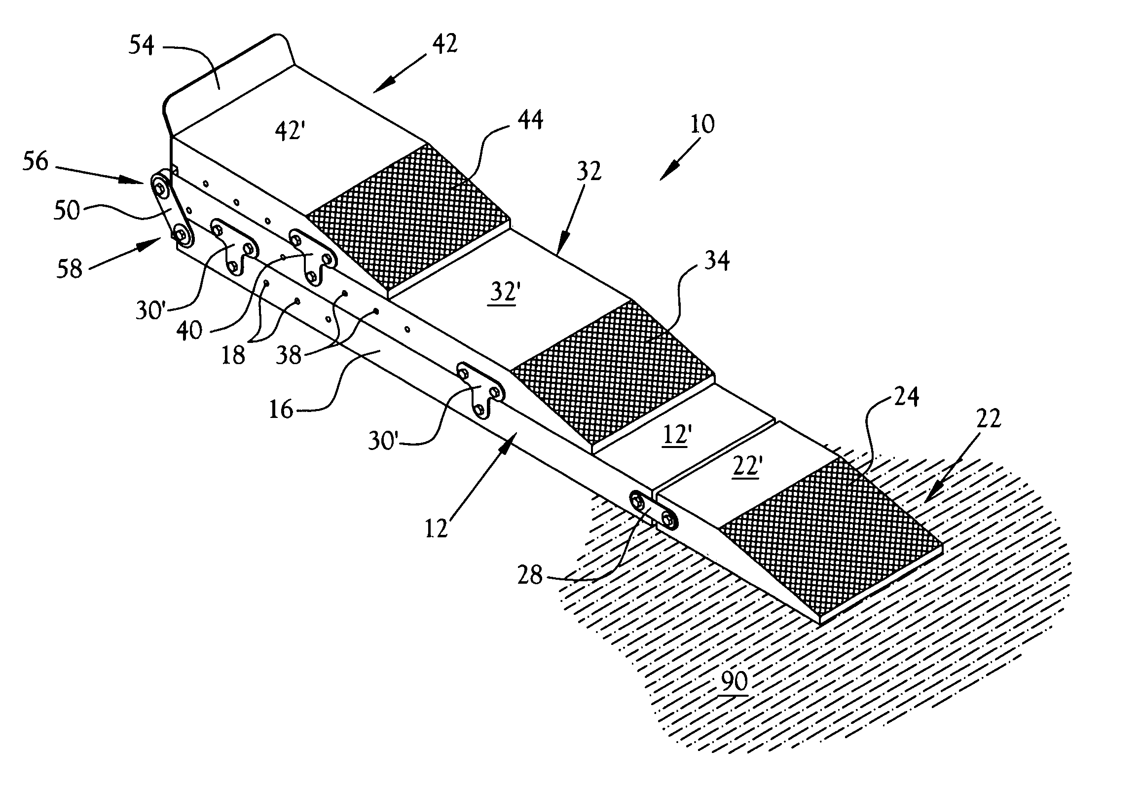
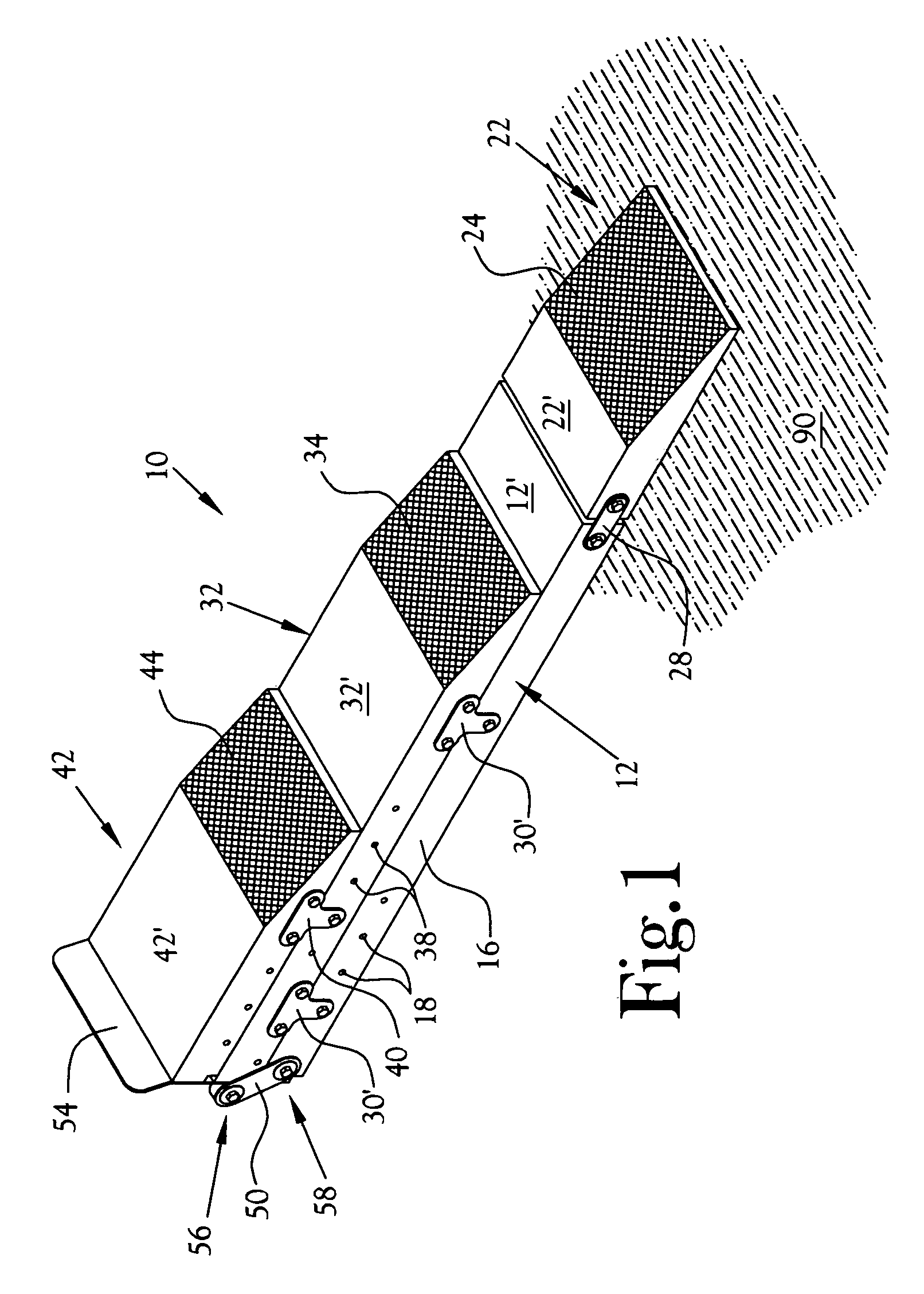
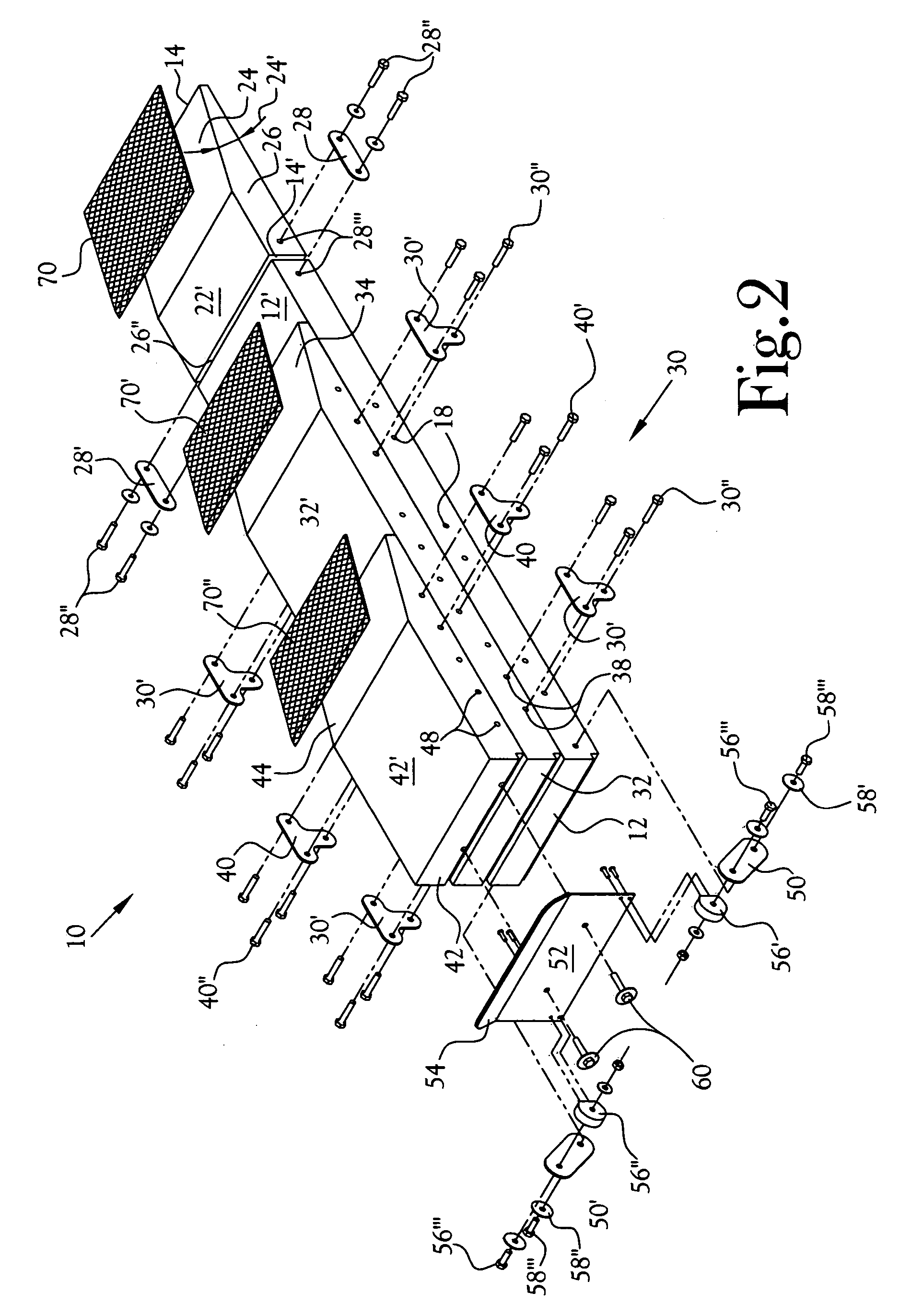
[0030]A portable modular wheel lift unit having a plurality of lift units is disclosed for lifting to a variety of heights for one or more wheels 80, 82 of a vehicle front and / or rear 84, 86 having front, side and / or rear body portions extended to a low height above a ground surface 90. The wheel lift is illustrated at 10 in FIGS. 1–9, and includes a plurality of modular segments which are positionable from a right or left lateral approach onto a base lift unit 12 in order to provide a variety of lift heights for lifting one or more wheels 80, 82 of a vehicle. A method of operation is also disclosed for lifting at least one vehicle wheel 80, 82 utilizing a portable modular wheel lift 10 which is sequentially assembled by lateral positioning the stackable components from either a right or left side of the base lift unit 12, regardless of whether a vehicle wheel 80, 82 is positioned on a ramp surface or a horizontal support surface of the base lift unit 12.

[0031]The base lift unit 12 ...


PUM


Abstract

A modular wheel lift provides elevation of a vehicle wheel enclosed by body portions of a low height above the ground. A base lift unit includes a lift surface height selected to be less than the body portions height. A ramp unit is aligned and hingedly attached to one end of the base lift unit, to allow rotational movement of a wheel to the base lift surface. Additional lift units having ramp ends and progressively decreasing lengths are laterally positioned and stacked on the base lift surface. Side brackets are releasably positioned along either side surface to secure the stacked additional lift units to allow rotational movement of the vehicle wheel to an uppermost lift surface. A method of assembly and elevating includes laterally positioning and stacking a plurality of lift units having progressively shorter lengths to provide lifting of a vehicle wheel without disruption of the vehicle body portions.

Description

CROSS-REFERENCE TO RELATED APPLICATIONS[0001]Not ApplicableSTATEMENT REGARDING FEDERALLY SPONSORED RESEARCH OR DEVELOPMENT[0002]Not ApplicableBACKGROUND OF THE INVENTION[0003]1. Field of Invention[0004]This invention pertains to portable devices for lifting a vehicle wheel. More particularly, this invention pertains to portable devices for lifting wheels of lowered vehicles.[0005]2. Description of the Related Art[0006]Portable ramp devices utilized for lifting one or more vehicle wheels off of a ground surface are available to facilitate changing a tire, for adjusting the vehicle suspension system, and to allow maintenance activities or inspection activities underneath the vehicle. Prior art portable ramp devices generally require at least about seven to eight inches clearance between the ground and the vehicle side frame, front bumper or rear bumper, depending on the preferred positioning for the ramp device. Due to the height above the ground of prior portable ramp devices, each r...

Claims


Application Information

Patent Timeline
Patent Type & Authority Patents(United States)
IPC IPC(8): E02C3/00
CPCB66F7/243
Inventor BRANSTETTER, D. ROGER
Owner BRANSTETTER ANN
Learn More