Fluid dynamic bearing configured with an orbital ring for higher efficiency

a technology orbital rings, which is applied in the field can solve the problems of reducing the power consumption of fluid dynamic bearings, reducing the stiffness of bearings, and so as to achieve the effect of not reducing the overall stiffness of the assembly

Inactive Publication Date: 2006-07-11
SEAGATE TECH LLC
View PDF4 Cites 11 Cited by
  • Summary
  • Abstract
  • Description
  • Claims
  • Application Information

AI Technical Summary

Benefits of technology

[0010]The disclosed assembly is especially useful in fluid dynamic bearing motors. One advantage of the disclosed assembly is that a fluid dynamic bearing motor using the disclosed assembly consumes substantially less power than a fluid dynamic bearing motor not using the disclosed assembly. Further, if the gap sizes of the fluid dynamic bearings included in the disclosed assembly are decreased appropriately, the overall stiffness of the assembly does not decrease appreciably.

Problems solved by technology

As persons skilled in the art are aware, an ongoing challenge in fluid dynamic bearing motor design is balancing the tradeoff between motor performance and power consumption.
On the other hand, however, increasing bearing stiffness results in greater power consumption because of increased viscous losses in the bearings.
Conversely, decreasing the power consumption of the fluid dynamic bearings typically requires a substantial decrease in bearing stiffness and, hence, decreased motor performance.

Method used


Image

  • Fluid dynamic bearing configured with an orbital ring for higher efficiency
  • Fluid dynamic bearing configured with an orbital ring for higher efficiency
  • Fluid dynamic bearing configured with an orbital ring for higher efficiency

Examples


Embodiment Construction

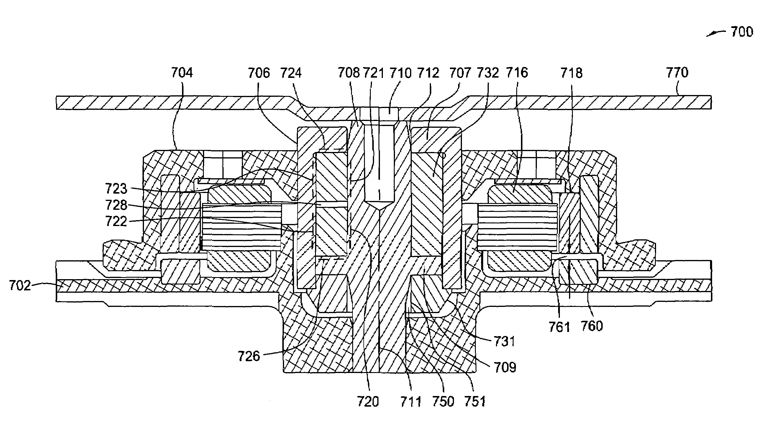
[0021]FIG. 3 is a cross-sectional view illustrating an orbital ring 308 in a fluid dynamic bearing motor assembly 300, according to one embodiment of the invention. As shown, fluid dynamic bearing motor assembly (hereinafter also referred to as “FDB motor assembly”) 300 may include, without limitation, a hub 306, orbital ring 308, a shaft 310, a stator assembly 314 (partially shown), a magnet 316, a base 320, a seal 322 and a displacement limiter 326.

[0022]Shaft 310 is attached to base 320 and supports FDB motor assembly 300. In this embodiment, shaft 310 is stationary. As described in further detail below, in other embodiments, shaft 310 may rotate about a rotational axis 311. Hub 306 is configured to rotate about rotational axis 311. Specifically, magnet 316 is attached to hub 306, and the electromagnetic interaction between magnet 316 and stator assembly 314 causes hub 306 to rotate. As hub 306 rotates, fluid dynamic journal bearings 360 and 362 radially support hub 306, and flui...


PUM

PropertyMeasurementUnit
angular velocityaaaaaaaaaa
pressureaaaaaaaaaa
stiffness-to-power ratioaaaaaaaaaa

Abstract

A fluid dynamic bearing assembly is described. In one embodiment, the assembly includes an inner member. The assembly further includes an outer member configured to rotate about a rotational axis at a first angular velocity. The assembly also includes an orbital ring disposed between the inner member and the outer member. The orbital ring is configured to rotate about the rotational axis at a second angular velocity, which is less than the first angular velocity.

Description

CROSS-REFERENCE TO RELATED APPLICATION[0001]This application relates to, and claims the priority benefit of, U.S. Provisional Patent Application No. 60 / 415,152, titled “Orbital Ring Fluid Dynamic Bearing Motor,” filed on Sep. 30, 2002. The subject matter of the related application is hereby incorporated by reference.BACKGROUND OF THE INVENTION[0002]1. Field of the Invention[0003]This invention relates generally to fluid dynamic bearings and more specifically to a fluid dynamic bearing assembly configured with an orbital ring that rotates at a fractional speed, thereby increasing the overall stiffness-to-power ratio of the assembly.[0004]2. Description of the Background Art[0005]FIG. 1 is an exploded perspective view illustrating a prior art magnetic disc drive 100. As shown, magnetic disc drive 100 may include, without limitation, a housing 105, a shaft 130, discs 135 and a suspension arm assembly 150. Housing 105 includes a base 110 that is attached to a cover 115. In addition, a s...

Claims


Application Information

Patent Timeline
Patent Type & Authority Patents(United States)
IPC IPC(8): F16C17/10F16C17/18F16C33/10G11B19/20
CPCF16C17/107F16C17/18G11B19/2018F16C33/107F16C2370/12Y10S384/901G11B19/20
Inventor AIELLO, ANTHONY JOSEPHKLOEPPEL, KLAUS DIETER
Owner SEAGATE TECH LLC
Why Eureka
Try Eureka