Tangential cutting insert and insert holder

a cutting insert and insert holder technology, applied in the direction of cutting inserts, shaping cutters, manufacturing tools, etc., can solve the problem of limited cutting depth

Active Publication Date: 2006-07-11
ISCAR LTD
View PDF15 Cites 72 Cited by
  • Summary
  • Abstract
  • Description
  • Claims
  • Application Information

AI Technical Summary

Benefits of technology

[0044]If desired, each end surface of the cutting insert further comprises two frustums extending away from the median plane located on either side of the major plane, and the top surface of the shim, in accordance with the present invention, further comprises a raised area being a portion of the top surface of the shim protruding from the top surface of the shim; wherein
[0045]the two frustums of the non-operative end surface abut the raised area of the top surface of the shim.

Problems solved by technology

Although the cutting insert is substantially square and although it offers eight cutting corners, its depth of cut is limited.

Method used


Image

  • Tangential cutting insert and insert holder
  • Tangential cutting insert and insert holder
  • Tangential cutting insert and insert holder

Examples


Embodiment Construction

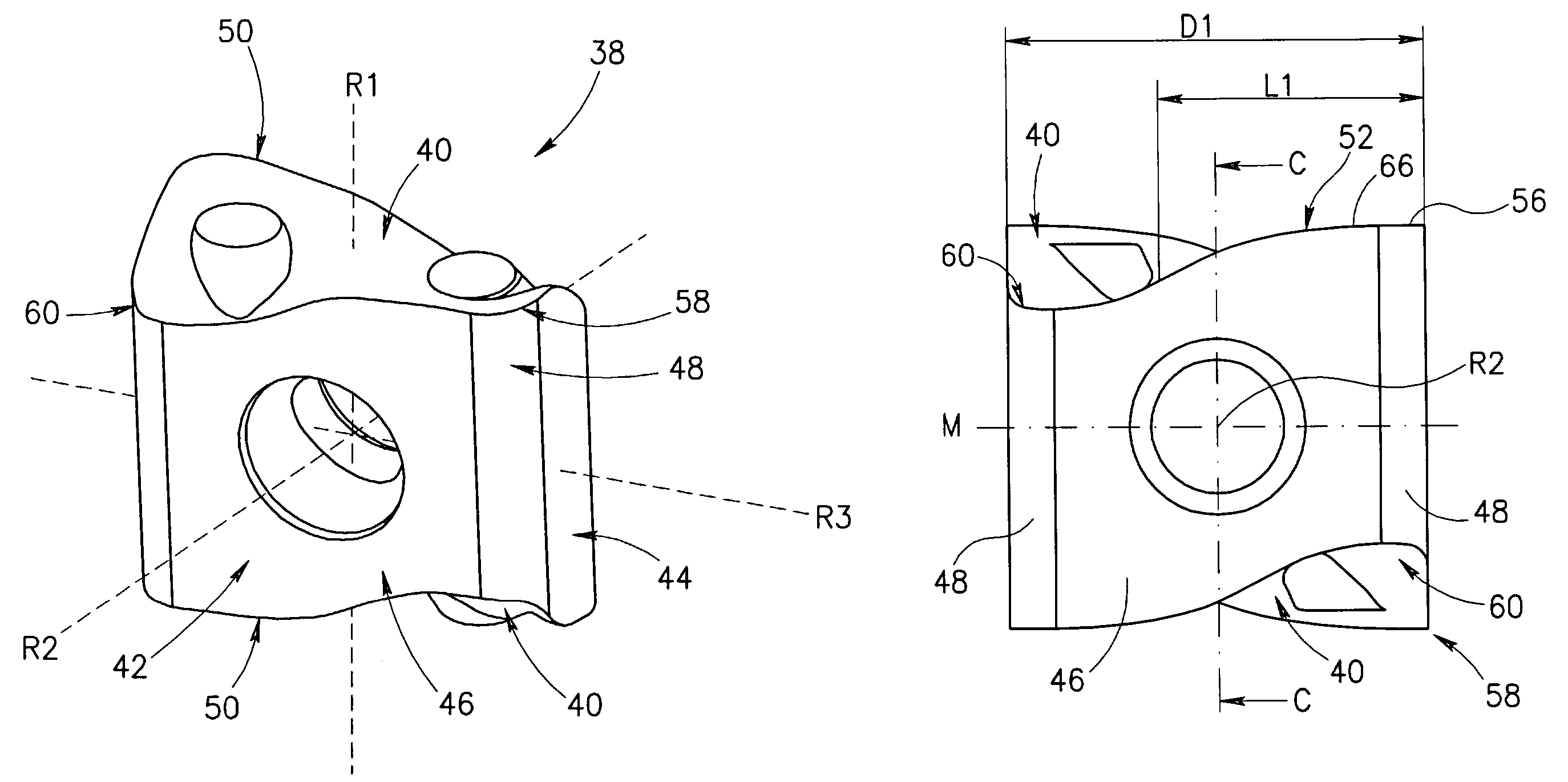
[0063]Attention is first drawn to FIGS. 4 to 8, showing a tangential indexable cutting insert 38 in accordance with present invention. The cutting insert 38 is generally manufactured by form pressing and sintering a cemented carbide, such as tungsten carbide, and can be coated or uncoated. The cutting insert 38 is generally rectangular in an end view and comprises two identical end surfaces 40, and a peripheral side surface 42 extending between the end surfaces 40. The cutting insert 38 and the end surfaces 40 have 180° rotational symmetry about a first axis R1 that passes through the end surfaces 40. Since the end surfaces 40 are identical, only one will be described, it being understood that the other end surface 40 has identical structure.

[0064]The peripheral side surface 42 comprises two opposed identical minor side surfaces 44, two opposed identical major side surfaces 46, and four opposed corner side surfaces 48. Adjacent major and minor side surfaces 46, 44 merge at a common ...


PUM

PropertyMeasurementUnit
distance d2aaaaaaaaaa
distance d1aaaaaaaaaa
angleaaaaaaaaaa

Abstract

A tangential indexable cutting insert can be used for metal cutting processes in general and for radial and axial turning of a stepped square shoulder in particular. The cutting insert exhibits 180° rotational symmetry about three mutually perpendicular axes. The cutting insert has generally “S”-shaped cutting edges extending between raised and lowered corners. The cutting edges and side surfaces are concave in an end view of the cutting insert. The cutting insert enables radial and axial turning operations of a square shoulder with unlimited depth of cut.

Description

FIELD OF THE INVENTION[0001]The present invention relates to a tangential indexable cutting insert for use in metal cutting processes in general and for radial and axial turning of a stepped square shoulder in particular.BACKGROUND OF THE INVENTION[0002]Tangential cutting inserts, also known as on-edge, or lay down, cutting inserts, are oriented in an insert holder in such a manner that during a cutting operation on a workpiece the cutting forces are directed along a major (thicker) dimension of the cutting insert. An advantage of such an arrangement being that the cutting insert can withstand greater cutting forces than when oriented in such a manner that the cutting forces are directed along a minor (thinner) dimension of the cutting insert. Another advantage of such an arrangement is that with the minor dimension directed perpendicular to the cutting forces it is possible to manoeuvre the cutting insert between obstacles close to the workpiece.[0003]For turning a stepped square s...

Claims


Application Information

Patent Timeline
Patent Type & Authority Patents(United States)
IPC IPC(8): B23B27/16B23B27/14B23B27/08
CPCB23B27/08B23B27/1622B23B27/1614Y10T407/1924B23B2200/0423B23B2200/082B23B2200/083B23B2200/121B23B2200/123B23B2200/161B23B2200/202B23B2200/207B23B2200/3627B23B2200/369B23B2205/12B23B2205/16Y10T407/235Y10T407/23Y10T407/2274B23B27/16
Inventor HECHT
Owner ISCAR LTD
Why Eureka
Try Eureka