Chain tensioner

a chain tensioner and chain technology, applied in the direction of belts/chains/gearings, mechanical equipment, belts/chains/gearings, etc., can solve the problems of deterioration of the follow-up of the tensioner lifter for the transmission chain, increased etc., to achieve satisfactory maintenance, reduce the load and enhance the oscillation absorption function of the tensioner lifter

Active Publication Date: 2006-07-11
HONDA MOTOR CO LTD
View PDF4 Cites 13 Cited by
  • Summary
  • Abstract
  • Description
  • Claims
  • Application Information

AI Technical Summary

Benefits of technology

[0007]The present invention is made in view of such a situation. It is an object of the present invention to provide a chain tensioner in which a load of a tensioner lifter is reduced, enhancing the oscillation absorption function of the tensioner lifter and the follow-up of the tensioner lifter for a transmission chain so that it may be satisfactorily maintained.
[0010]According to the first embodiment, the oscillation of the transmission chain can be absorbed by applying suitable flexibility to the tensioner arm. In addition, as the control arm is inserted between the tensioner arm and the tensioner lifter, the repulsion of the transmission chain for the tensioner arm is transmitted to the tensioner lifter after the repulsion is buffered by the suitable flexibility of the control arm and a load of the tensioner lifter can be reduced. Therefore, the follow-up of the transmission chain by the tensioner lifter can be satisfactorily performed, securing the desired useful life of the tensioner lifter.
[0012]According to the second embodiment, the tensioner arm can be greatly moved via the control arm at a relatively small stroke of a lifter rod of the tensioner lifter owing to the arm ratio of the control arm. As a result, the follow-up of the transmission chain by the tensioner lifter is further enhanced. In addition, the repulsion of the transmission chain is not only directly transmitted to the tensioner lifter but the useful life of the tensioner lifter can be extended.
[0015]According to the third embodiment, the contact ratio of the transmission chain and the driving or driven sprocket in the vicinity of the end of the tensioner arm is enhanced and the present invention can contribute to the enhancement of chain transmission efficiency.

Problems solved by technology

However, in the conventional type of tensioner lifter is directly oscillated by the tensioner arm, a load of the tensioner lifter is increased and the follow-up of the tensioner lifter for the transmission chain may be deteriorated.

Method used


Image

  • Chain tensioner
  • Chain tensioner
  • Chain tensioner

Examples


first embodiment

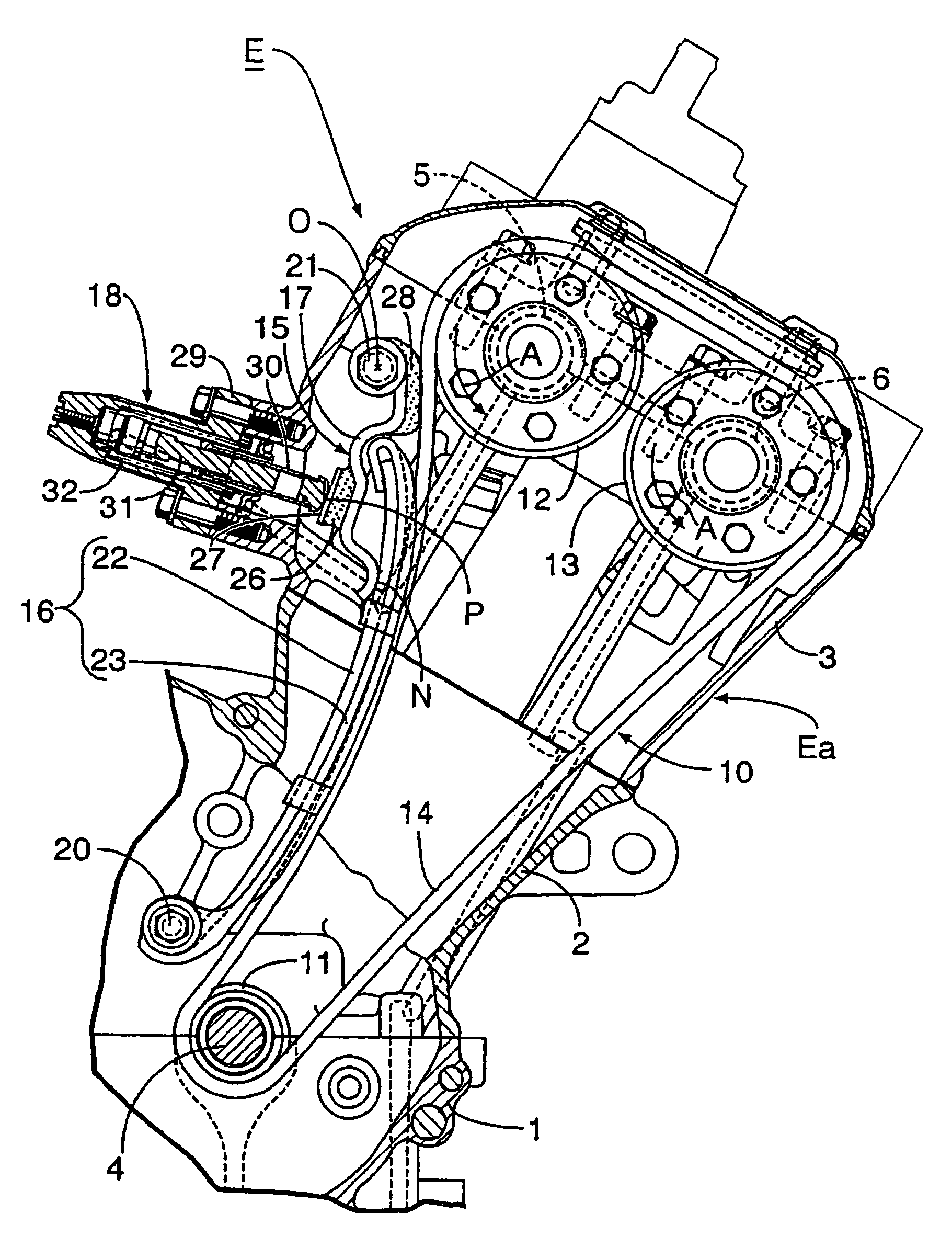
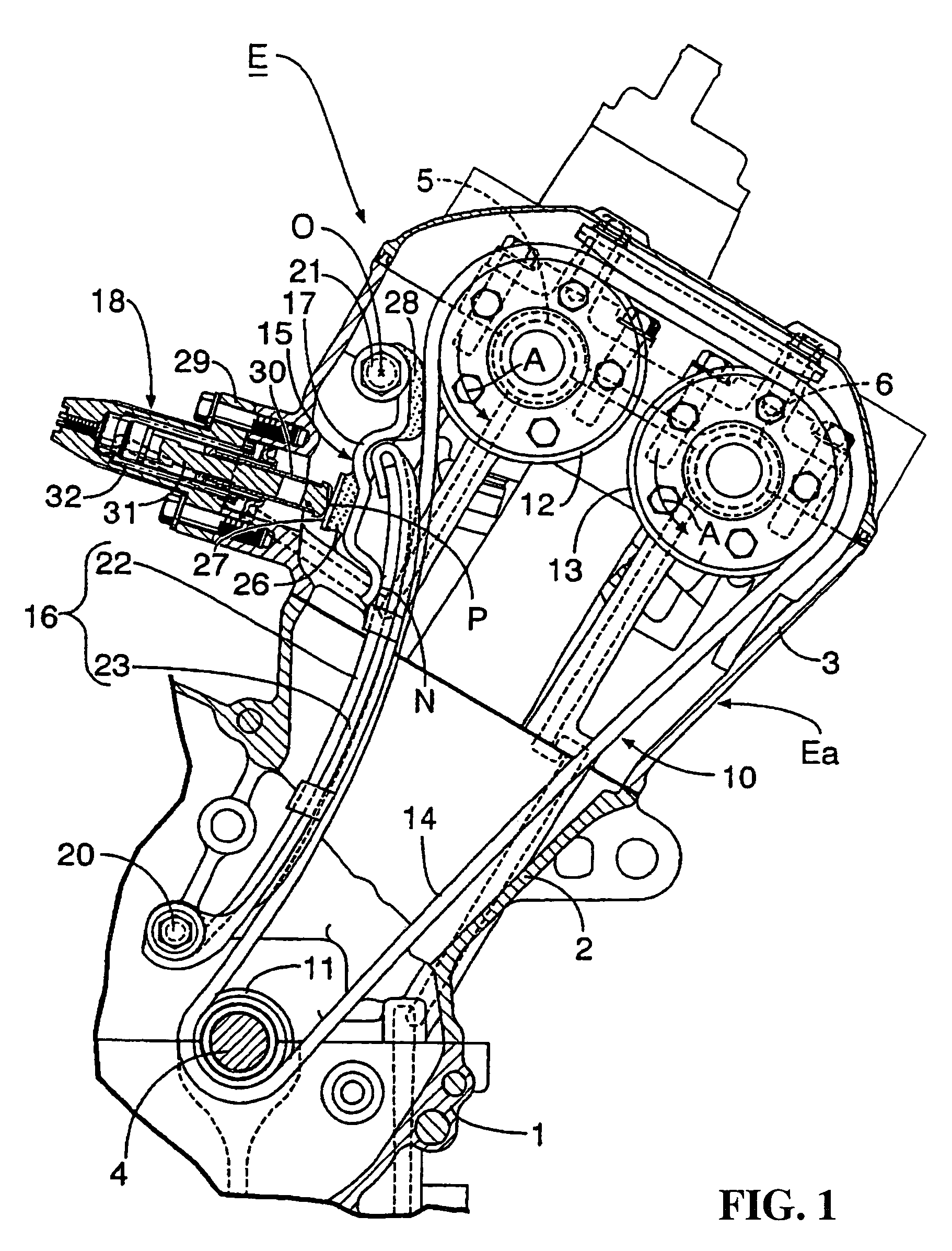
[0049]As described above, according to the present invention, in the chain tensioner provided with the tensioner arm rockably supported by fixed structure and slidably engaged with the outside on the loose side of the transmission chain without an end coupling the driving sprocket and the driven sprocket and the tensioner lifter supported by the fixed structure for pressing the tensioner arm on the side of the transmission chain, as the control arm rockably supported by the fixed structure for transmitting the pressure of the tensioner lifter to the tensioner arm is inserted between the tensioner arm and the tensioner lifter, the oscillation of the transmission chain can be absorbed by applying suitable flexibility to the tensioner arm. In addition, as the control arm is inserted between the tensioner arm and the tensioner lifter, the repulsion of the transmission chain for the tensioner arm is transmitted to the tensioner lifter after the repulsion is buffered by the suitable defle...

second embodiment

[0050]In addition, according to the present invention, as the point of the application of the pressure of the tensioner lifter upon the control arm is set to the middle of the center of the oscillation of the control arm and the point at which the control arm presses the tensioner arm, the tensioner arm can be greatly moved via the control arm at a relatively small stroke of the lifter rod of the tensioner lifter owing to the arm ratio of the control arm, as a result, the follow-up of the tensioner lifter for the transmission chain is further enhanced, and the repulsion of the transmission chain is not directly transmitted to the tensioner lifter but the useful life of the tensioner lifter can be extended.

third embodiment

[0051]Further, according to the present invention, as the pressing part for slidably pressing the outside of the transmission chain is provided to the control arm between the end of the tensioner arm and the sprocket in the vicinity of the end, the contact ratio of the transmission chain and the driving or driven sprocket close to the end of the tensioner arm is enhanced and chain transmission efficiency can be enhanced.


PUM


Abstract

To reduce a load of a tensioner lifter, enhancing the oscillation absorption function of the tensioner lifter in a chain tensioner. In a chain tensioner provided with a tensioner arm rockably supported by fixed structure and relatively slidably engaged with the outside on the loose side of a transmission chain without an end coupling a driving sprocket and a driven sprocket and a tensioner lifter supported by the fixed structure for pressing the tensioner arm on the side of the transmission chain, a control arm is rockably supported by the fixed structure for transmitting the pressure of the tensioner lifter to the tensioner arm. The control arm is inserted between the tensioner arm and the tensioner lifter.

Description

CROSS-REFERENCE TO RELATED APPLICATIONS[0001]The present application claims priority under 35 USC 119 to Japanese Patent Application Nos. 2002-266035 filed on Sep. 11, 2002 the entire contents thereof are hereby incorporated by reference.BACKGROUND OF THE INVENITON[0002]1. Field of the Invention[0003]The present invention relates to the improvement of a chain tensioner provided with a tensioner arm rockably supported by fixed structure and slidably engaged with the outside on the loose side of a transmission chain without an end coupling a driving sprocket and a driven sprocket and a tensioner lifter supported by fixed structure for pressing the tensioner arm upon the side of the transmission chain.[0004]2. Description of Background Art[0005]Such a chain tensioner is already known as disclosed in Japanese published examined patent application No. Sho63-29963, for example.[0006]In a conventional type chain tensioner, a tensioner lifter directly presses the back of a tensioner arm. To...

Claims


Application Information

Patent Timeline
Patent Type & Authority Patents(United States)
IPC IPC(8): F16H7/08
CPCF16H7/0848F16H2007/0872F16H2007/0859F16H2007/0812
Inventor FUJIKUBO, MAKOTOFURUYA, MASASHISONOBATA, AKIRAIBUKURO, HIDEO
Owner HONDA MOTOR CO LTD
Why Eureka
Try Eureka