Method and apparatus for making cigarette filters with a centrally located flavored element

a technology of flavored elements and filters, which is applied in the field of methods and apparatus for making cigarette filters, can solve the problems of inability to precisely control the position of flavored elements within the smoke filter, contamination of subsequent produced filters,

Inactive Publication Date: 2006-07-11
PHILIP MORRIS USA INC
View PDF37 Cites 260 Cited by
  • Summary
  • Abstract
  • Description
  • Claims
  • Application Information

AI Technical Summary

Benefits of technology

[0009]The positioning device is preferably provided with at least first and second inlets, with the continuous flavor element passing through the first inlet and the liquid flavorant being supplied through the second inlet. In a preferred embodiment, the positioning device is configured with a bend or “goose-neck” near the first inlet such that the continuous flavor element, in passing through the goose-neck, is maintained at the bottom of the positioning device for the rest of the way to the exit. This ensures that the flavor element will remain in the liquid flavorant that collects in the bottom of the positioning device, or is provided at an intermediate point along the passageway through the device.
[0011]In the case of traditional filter making equipment, the outlet of the positioning device can be positioned under the tongue, which is positioned downstream of a transport jet and an air funnel that form part of the converging device. The tongue guides the filter tow material in the final stage before it is converged to a rod form, and the positioning device guides the liquid flavorant and the continuous flavor element to a position relative to the tongue that ensures desired positioning of the continuous length of textile material in the finished filter rod.
[0014]The positioning device can be provided with fine-tune adjustments so that its final position relative to the converging filter tow material under the tongue of the filter making equipment can be precisely controlled. It is preferred to locate the continuous flavor element carrying liquid flavorant in the center of the path of maximum air flow through the finished cigarette filter rods. The outlet of the positioning device is preferably provided with a sufficient diameter to allow for passage of the continuous flavor element, such as continuous length of textile material carrying liquid flavorant without creating any undesirable back pressure in the positioning device and yet with the outlet of the positioning device being maintained at a small enough outer diameter such that it does not protrude too far into the path of converging filter tow material at the point where the filter tow material is being shaped by the tongue into the final rod form.

Problems solved by technology

It has been found in practicing the conventional methods for producing tobacco smoke filters that problems result when the use of a particular flavoring agent is to be terminated or when one flavoring agent is to be substituted for another.
These problems result because the spray booth within which the plasticizer is applied will be contaminated with the first flavoring agent employed, so that the subsequently produced filters would be contaminated unless production was stopped and the contaminated booth was cleaned or replaced.
Known methods for introducing a flavored element into the interior of a filter have also suffered from the disadvantage that flavorant is often not introduced in the proper amounts or at the proper location within the cigarette filter to achieve the desired effect on the smoke passing through the filter, and the position of the flavored element within the smoke filter could not be precisely controlled.

Method used


Image

  • Method and apparatus for making cigarette filters with a centrally located flavored element
  • Method and apparatus for making cigarette filters with a centrally located flavored element
  • Method and apparatus for making cigarette filters with a centrally located flavored element

Examples


Embodiment Construction

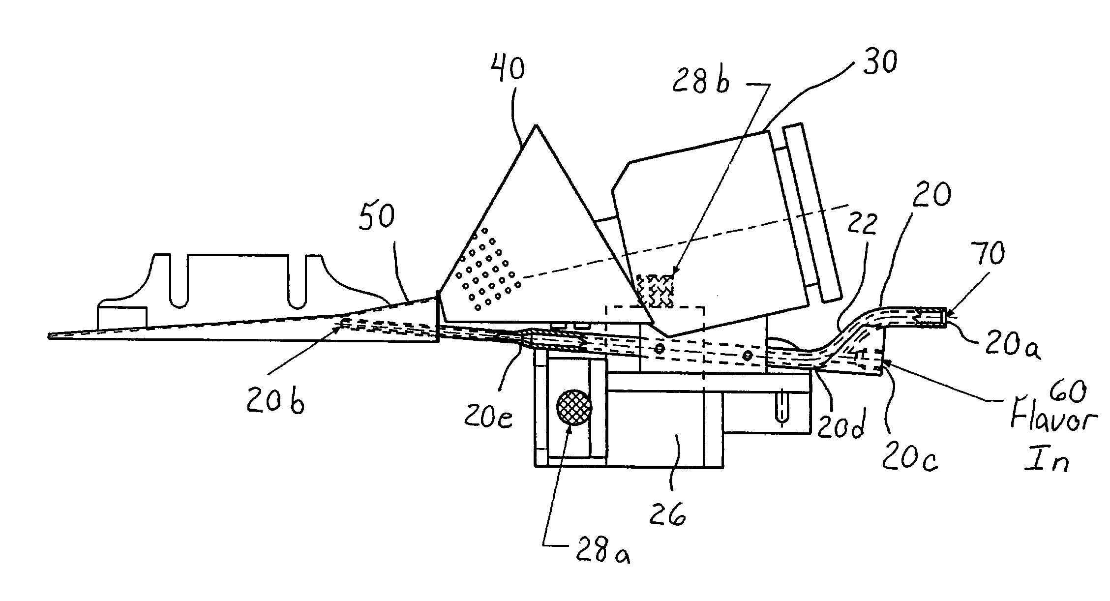
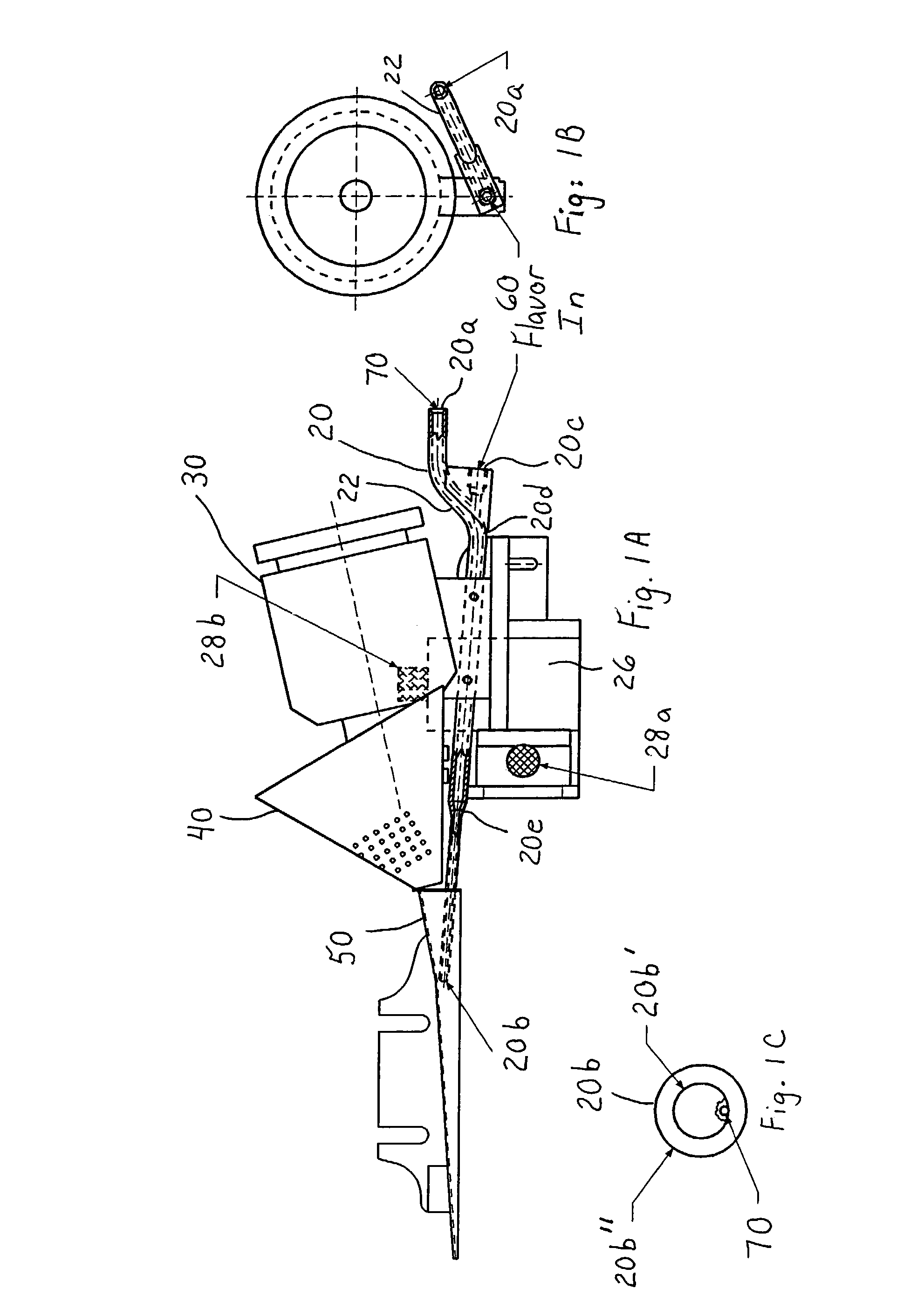
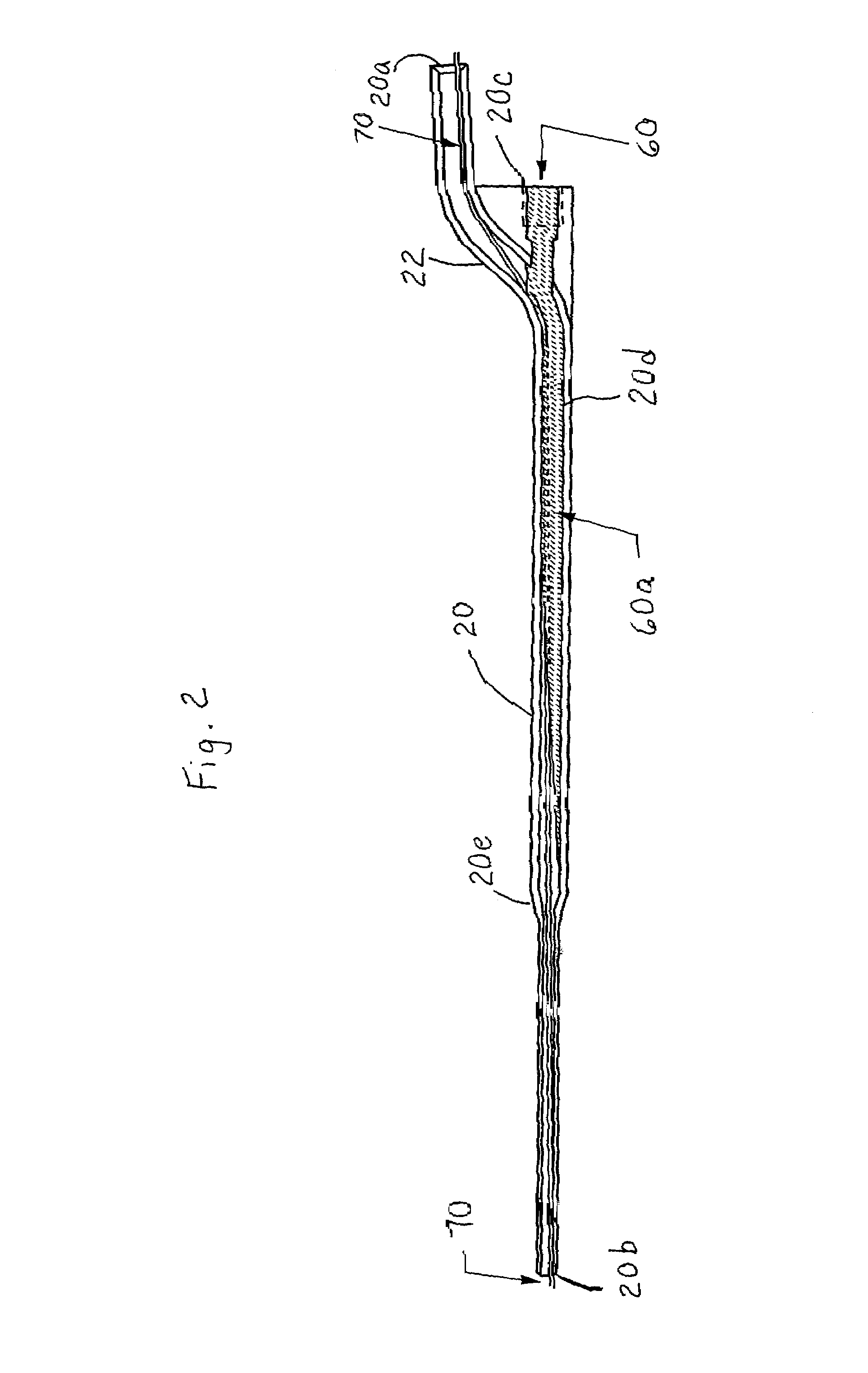
[0023]Referring initially to FIG. 1A, an embodiment of a positioning device according to the invention is combined with standard filter making equipment to provide for the positioning of a flavor element 70 that is approximately centered within a filter rod made from filter tow material. The positioning device 20 is located and adjustably positioned relative to the filter making equipment by bracket 26, horizontal adjustment knob 28a, and vertical adjustment knob 28b as shown in FIGS. 1A, 3A and 3B. The bracket 26 can hold the positioning device 20 in position relative to a transport jet 30 and an air funnel 40, with an outlet end 20b of the positioning device 20 being positioned under a tongue 50 that guides converging filter tow material exiting from the air funnel 40 into a standard garniture downstream of the outlet end 20b where the filter tow is shaped to rod form. The resulting continuous rod is then wrapped with a filter paper and the wrap is secured with a lapped and adhesi...


PUM


Abstract

A filter making apparatus includes a positioning device having a passageway therethrough, with the passageway guiding a continuous flavor element such as a continuous strand of textile material from an inlet of the passageway to an outlet of the passageway. A liquid flavorant is introduced into the passageway at a desired flow rate and the strand of material carries the supplied liquid flavorant out of the positioning device at a rate substantially equal to the desired flow rate. A portion of the passageway can form a bath of the liquid flavorant supplied to the passageway through a separate inlet at approximately atmospheric pressure. A portion of the positioning device guides the continuous strand of material through the bath, or guides the strand to pass along the bottom of the passageway, and the saturated or partially saturated strand of material then exits from an outlet of the passageway to a point in the path of filter tow material that is being converged to form a filter rod.

Description

[0001]This application claims benefit of 60 / 368,376 Mar. 29, 2002.FIELD OF THE INVENTION[0002]This invention relates to methods and apparatus for making cigarette filters that incorporate a centrally located flavored element which affects the taste of smoke drawn through the filter.BACKGROUND OF THE INVENTION[0003]Tobacco smoke filters have been produced that incorporate a flavor agent where the agent is applied uniformly over the filtering material before the filtering material is gathered and shaped to form the filter product. An example of these conventional filters includes a flavored tobacco smoke filter made from bonded cellulose acetate filamentary tow in which a liquid plasticizer such as triacetin is sprayed uniformly over the tow before it is gathered to its final rod form. The flavoring agent is normally dissolved in the liquid plasticizer, and the plasticizer effects the bonding between adjacent filaments.[0004]Other methods of producing cigarette filters are disclosed i...

Claims


Application Information

Patent Timeline
Patent Type & Authority Patents(United States)
IPC IPC(8): B31C13/00B31C99/00A24D3/02
CPCA24D3/022Y10S493/941
Inventor LANIER, JR., ROBERT C.CAMPBELL, STEVEN M.BELLAMAH, STEPHEN J.
Owner PHILIP MORRIS USA INC
Why Eureka
Try Eureka