Specimen sensing apparatus

a technology of sensing apparatus and specimens, which is applied in the direction of optical radiation measurement, instruments, machines/engines, etc., can solve the problem of not being able to sense specimens

Active Publication Date: 2006-07-18
IDS CO LTD
View PDF10 Cites 33 Cited by
  • Summary
  • Abstract
  • Description
  • Claims
  • Application Information

AI Technical Summary

Benefits of technology

[0008]1) A specimen contained in a container can be sensed easily

Problems solved by technology

It is not therefore suitable to sense a specimen contained in

Method used


Image

  • Specimen sensing apparatus
  • Specimen sensing apparatus

Examples


embodiment

Features of Embodiment

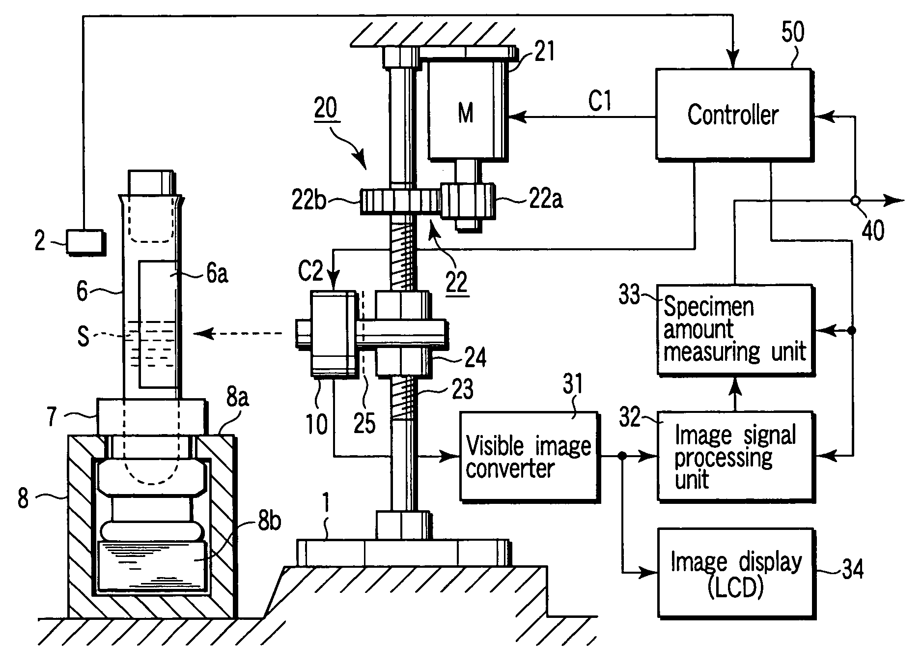
[0024][1] A specimen sensing apparatus according to an embodiment of the present invention, comprises:

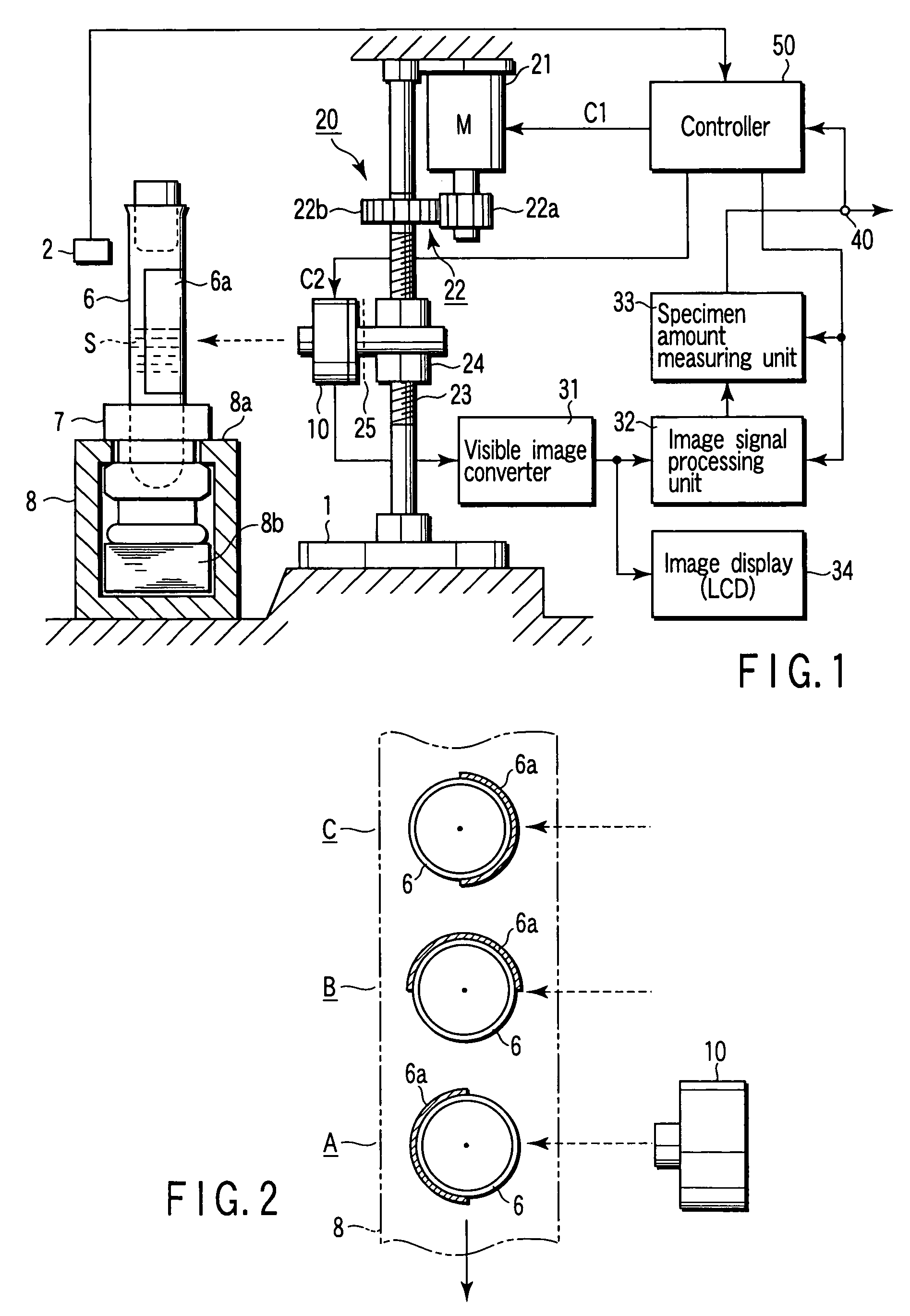
[0025]a specimen container 6 which is vertically positioned by a container holder 7 of a columnar rack type and conveyed by a belt conveyor 8;

[0026]an infrared CCD camera 10 configured to pick up an infrared image of the specimen container 6;

[0027]a visible image converter 31 which converts the infrared image picked up by the infrared CCD camera 10 into a visible image;

[0028]an image signal processing unit 32 which processes and converts one of the infrared image or the visible image into a signal that is suitable to measure a specimen amount; and

[0029]a specimen amount measuring unit 33 which measures an amount of specimen contained in the specimen container 6 in response to the signal processed by the image signal processing unit 32.

[0030]In the specimen sensing apparatus described above, the infrared CCD camera 10 photographs and senses a specimen contained ...


PUM


Abstract

A specimen sensing apparatus according to the present invention includes a specimen container which is vertically positioned by a container holder of a columnar rack type and conveyed by a belt conveyor, an infrared CCD camera configured to pick up an infrared image of the specimen container, a visible image converter which converts the infrared image picked up by the infrared CCD camera into a visible image, an image signal processing unit which processes and converts one of the infrared image and the visible image into a signal that is suitable to measure a specimen amount, and a specimen amount measuring unit which measures an amount of specimen contained in the specimen container in response to the signal processed by the image signal processing unit.

Description

CROSS-REFERENCE TO RELATED APPLICATIONS[0001]This application is based upon and claims the benefit of priority from the prior Japanese Patent Application No. 2002-382232, filed Dec. 27, 2002, the entire contents of which are incorporated herein by reference.BACKGROUND OF THE INVENTION[0002]1. Field of the Invention[0003]The present invention relates to a specimen sensing apparatus for sensing a specimen such as blood, which is contained in a container such as a test tube.[0004]2. Description of the Related Art[0005]Jpn. Pat. Appln. KOKAI Publication No. 2002-323479 discloses a specimen sensing apparatus as described above. In this apparatus, a sensing coil is fitted to a test tube containing serum and clot that are separated from each other by a silicon-separating agent. The sensing coil and test tube are moved relative to each other while the sensing coil is being supplied with a measured signal having a given frequency. Based on variations in the level of the measured signal, a se...

Claims


Application Information

Patent Timeline
IPC IPC(8): G01F23/00G01F23/292G01N33/48G01N33/483
CPCG01F23/2921G01N21/3577G01N21/35
Inventor ITOH, TERUAKI
Owner IDS CO LTD
Why Eureka
Try Eureka