Battery tester capable of predicting a discharge voltage/discharge current of a battery

a battery and tester technology, applied in secondary cells servicing/maintenance, instruments, electrochemical generators, etc., can solve the problem of general categorization or test results that are insufficient to predict whether the battery is discharged or no

Active Publication Date: 2006-07-25
MIDTRONICS
View PDF316 Cites 117 Cited by
  • Summary
  • Abstract
  • Description
  • Claims
  • Application Information

AI Technical Summary

Problems solved by technology

However, such general categorizations or test results are insufficient for predicting whether the battery is capable of providing a sufficient voltage and / or current to start a vehicle in which the battery is employed, for example.

Method used


Image

  • Battery tester capable of predicting a discharge voltage/discharge current of a battery
  • Battery tester capable of predicting a discharge voltage/discharge current of a battery
  • Battery tester capable of predicting a discharge voltage/discharge current of a battery

Examples


Embodiment Construction

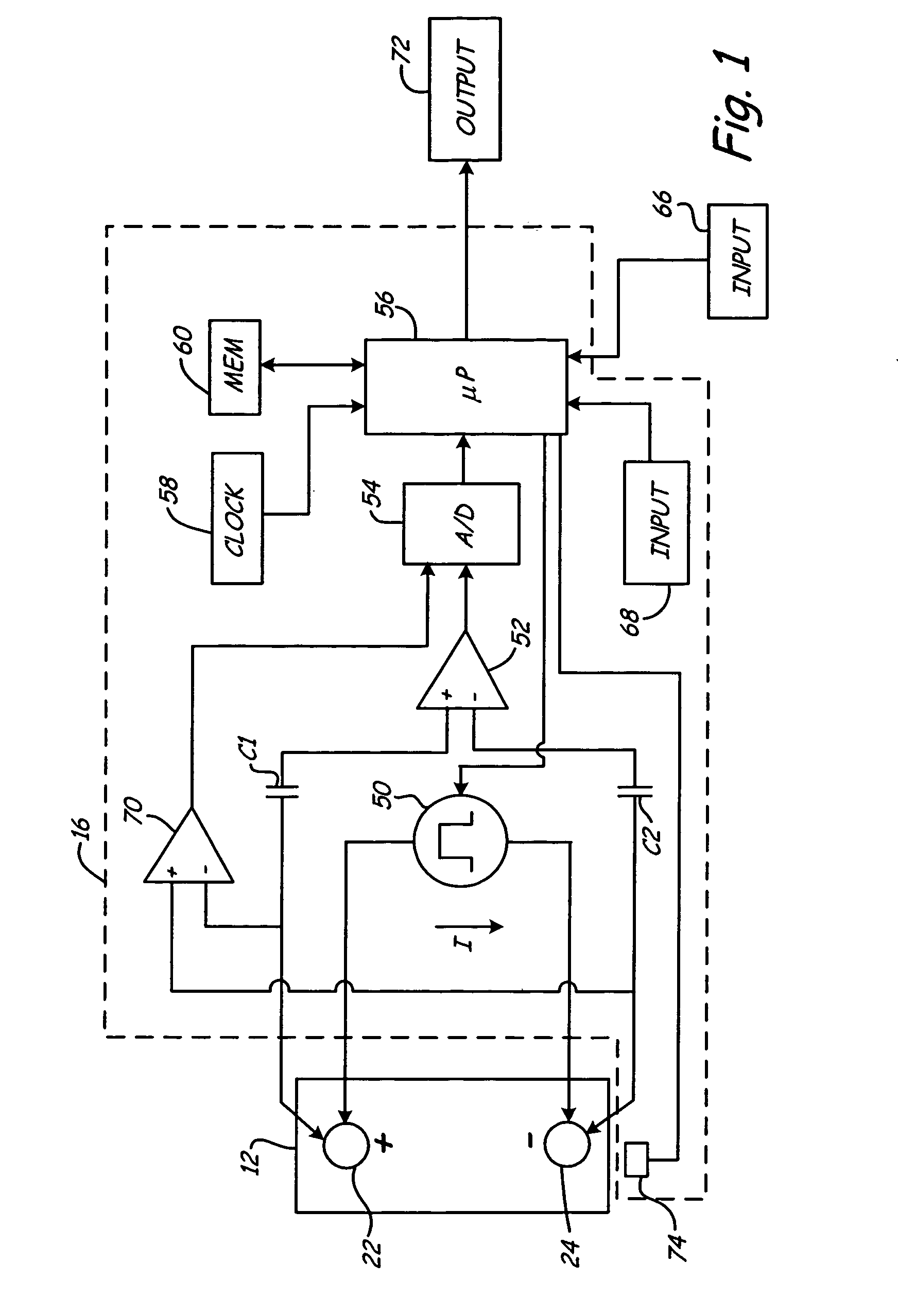
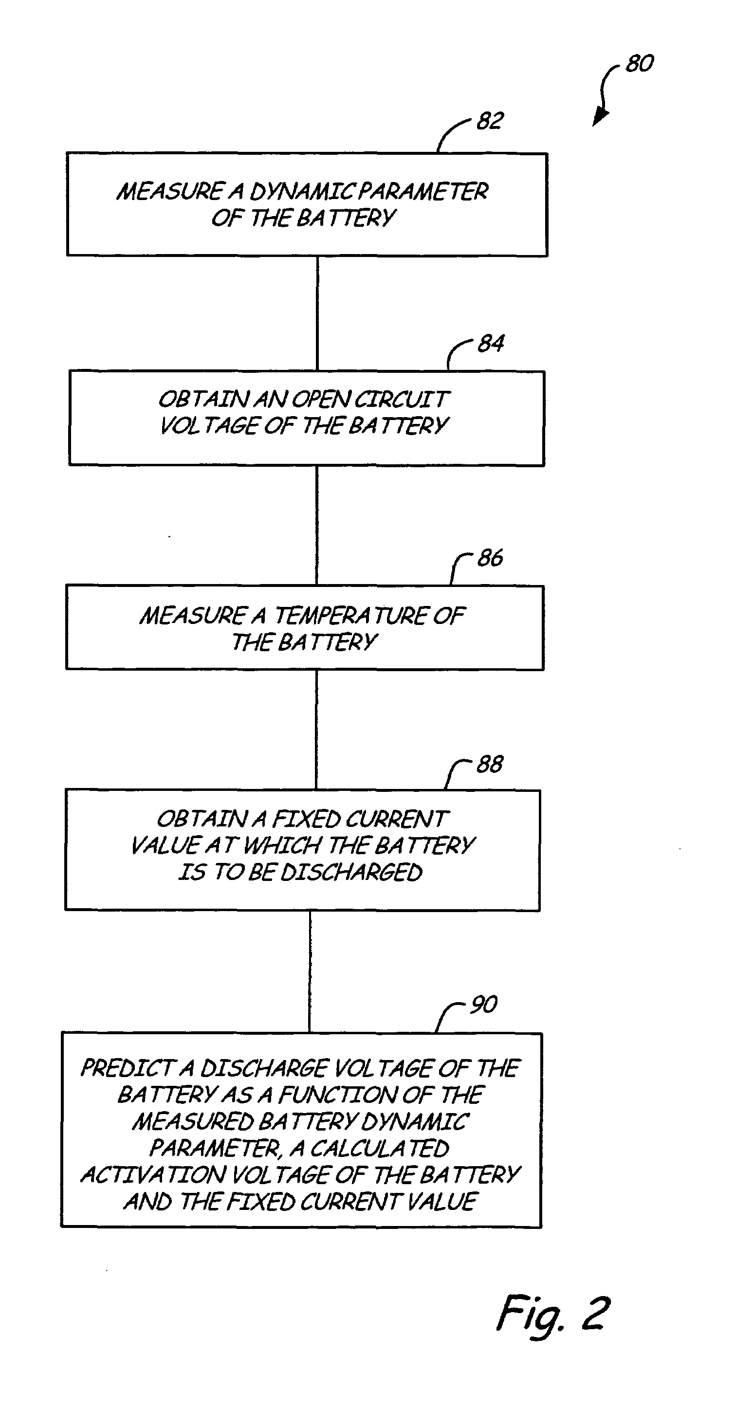
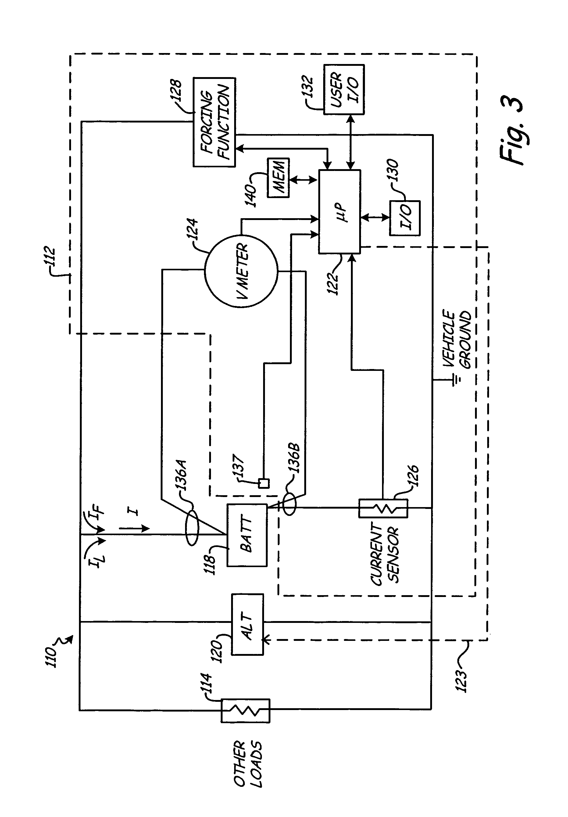
[0008]The present invention provides a method and apparatus for determining vehicle battery test outputs that are a function of battery temperature and / or the state of discharge of the battery. The outputs provided include a discharge voltage (instantaneous voltage akin to a vehicle starting voltage that the vehicle battery will deliver) at a fixed current, and a discharge current (instantaneous current akin to a vehicle starting current that the vehicle battery will deliver) at a fixed voltage.

[0009]In accordance with the present invention, the discharge voltage and discharge current predictions can be made over a wide range of conditions (battery temperature, state of discharge, etc.) using a non-intrusive test method (no high current loads). The non-intrusive test method includes measuring the battery to obtain a battery dynamic parameter such as conductance of the battery and utilizing the conductance and other information about the battery, discussed further below, to predict t...


PUM

PropertyMeasurementUnit
open circuit voltageaaaaaaaaaa
currentaaaaaaaaaa
activation voltageaaaaaaaaaa

Abstract

A method and apparatus is provided for determining how a vehicle battery would perform when used to start a vehicle. A discharge voltage / current of the battery is predicted as a function of a battery dynamic parameter, an open circuit voltage of the battery, a battery temperature and a fixed current / voltage value at which the battery is to be discharged. This discharge voltage / current value is compared to a minimum starting voltage / current required to start the vehicle in which the battery is employed and an output indicative of a starting capability of the battery is provided.

Description

CROSS REFERENCE TO RELATED APPLICATIONS[0001]The present application is based on and claims the benefit of U.S. provisional patent application Ser. No. 60 / 408,542, filed Sep. 5, 2002, and U.S. provisional patent application Ser. No. 60 / 437,224, filed Dec. 31, 2002, the contents of which are hereby incorporated by reference in its entirety.[0002]BATTERY TESTING DEVICE WITH AUTOMATIC VOLTAGE SCALING TO DETERMINE DYNAMIC CONDUCTANCE; U.S. Pat. No. 4,912,416, issued Mar. 27, 1990, to Champlin, entitled ELECTRONIC BATTERY TESTING DEVICE WITH STATE-OF-CHARGE COMPENSATION; U.S. Pat. No. 5,140,269, issued Aug. 18, 1992, to Champlin, entitled ELECTRONIC TESTER FOR ASSESSING BATTERY / CELL CAPACITY; U.S. Pat. No. 5,343,380, issued Aug. 30, 1994, entitled METHOD AND APPARATUS FOR SUPPRESSING TIME VARYING SIGNALS IN BATTERIES UNDERGOING CHARGING OR DISCHARGING; U.S. Pat. No. 5,572,136, issued Nov. 5, 1996, entitled ELECTRONIC BATTERY TESTER WITH AUTOMATIC COMPENSATION FOR LOW STATE-OF-CHARGE; U.S...

Claims


Application Information

Patent Timeline
Patent Type & Authority Patents(United States)
IPC IPC(8): G01N27/416G01R31/36H01MH01M10/42H01M10/46H01M10/48
CPCH01M10/486G01R31/3693G01R31/3675G01R31/362G01R31/3648G01R31/3647G01R31/374G01R31/3835Y02E60/10
Inventor KLANG, JAMES K.FANG, GREGORY P.
Owner MIDTRONICS
Why Eureka
Try Eureka