Integral manifold for liquid material dispensing systems

a technology of liquid material and manifold, which is applied in the direction of liquid transferring device, lighting and heating apparatus, immersion heating arrangement, etc., can solve the problems of increasing manufacturing costs, the need to stock multiple service parts, and the inability to compact dispensers, so as to minimize the thermal effect and minimize the effect of heat variation

Active Publication Date: 2006-07-25
NORDSON CORP
View PDF13 Cites 16 Cited by
  • Summary
  • Abstract
  • Description
  • Claims
  • Application Information

AI Technical Summary

Benefits of technology

[0008]A first temperature sensor is positioned in the manifold body at a location such that the first temperature sensor senses a temperature approximating the temperature of the process air provided to the modules from the process air passages, while minimizing the thermal effects of the second heating member on the first temperature sensor. A second temperature sensor is positioned in the manifold body at a location such that the second temperature sensor senses a temperature approximating the temperature of the liquid material provided to the modules from the liquid passages, while minimizing the thermal effects of the first heating member on the second temperature sensor. Advantageously, the first and second heating members are comprised of identical heating elements. First and second embodiments are disclosed in which the first and second heating members respectively extend substantially parallel to and transverse to the longitudinal extent of the manifold body. The manifold body further includes first and second ends each having fastening elements for coupling the manifold body to another manifold body, in side-by-side relation, to expand the number of dispensing modules of the dispensing system. This feature is especially adapted for the embodiment having transversely extending heating members.
[0009]The first heating member or process air heating member preferably further comprises an elongate cylindrical member. The cylindrical member may be a cartridge style heating element of an appropriate diameter, but in the preferred embodiment, the elongate cylindrical member includes a lengthwise extending central passage and an elongate, electrically operated variable heating element is positioned within the central passage. A groove is located on an outer surface of the cylindrical member and extends at least substantially around the circumference of the elongate cylindrical member. The groove is configured to receive process air to be heated by the elongate cylindrical member and communicates with the gap. The process air is heated by the manifold block on one side of the gap and by the first heating member on the opposite side of the gap. Since the manifold block is directly heated by the second heating member, the load for heating the process air is shared between the first and second heating members. Also, since the first heating member, e.g., the elongate cylindrical member, is spaced from the manifold block by the aforementioned gap, the heat supplied to the process air is effectively carried away by the process air moving through the gap. This minimizes the effect of variations in the heat supplied to the process air by the first heating member on the liquid sections of the manifold body. Thus, the set point temperature of the liquid may be more precisely maintained as the process air temperature is varied by controlling the power to the first heating member.

Problems solved by technology

This in turn contributes to increased manufacturing costs and the need to stock multiple service parts.
Having separate air and liquid material manifolds also inhibits making the dispensers compact in size.
Because the air and liquid material heaters are separately controlled, heat generated from one heater can interfere with the temperature control of the other material.
Finally, a dispenser having separate manifolds increases manufacturing time due to the need to couple together the individual manifolds to produce the adhesive dispenser.
Such modular adhesive dispensers present unique challenges such as maintaining uniform heating across all modules so that liquid material is uniformly dispensed to the substrate, particularly from dispensing modules located at the ends of each manifold where less heat from the manifold heaters is transferred to the liquid material due to heat losses through the ends of the manifold.

Method used


Image

  • Integral manifold for liquid material dispensing systems
  • Integral manifold for liquid material dispensing systems
  • Integral manifold for liquid material dispensing systems

Examples


Embodiment Construction

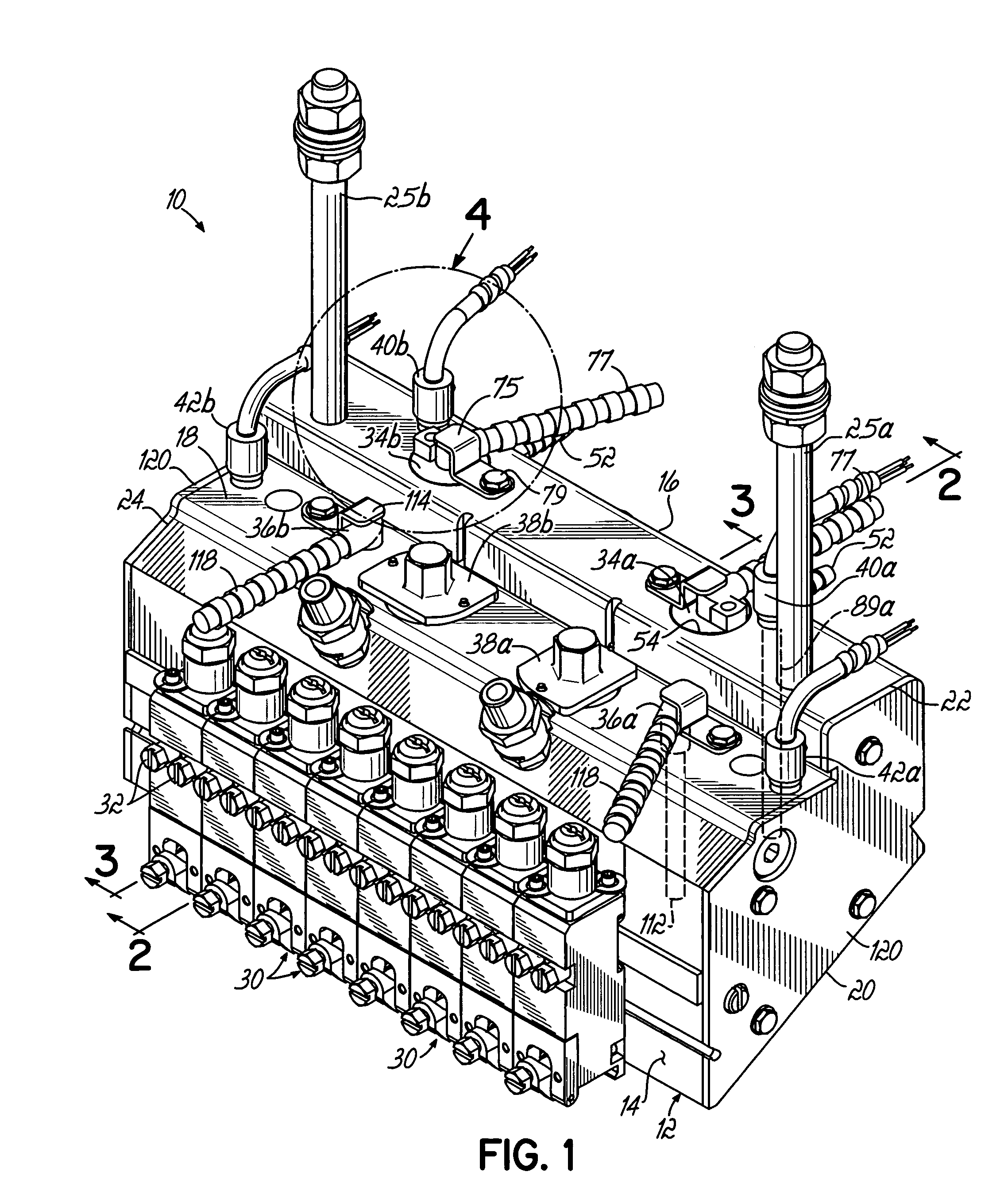
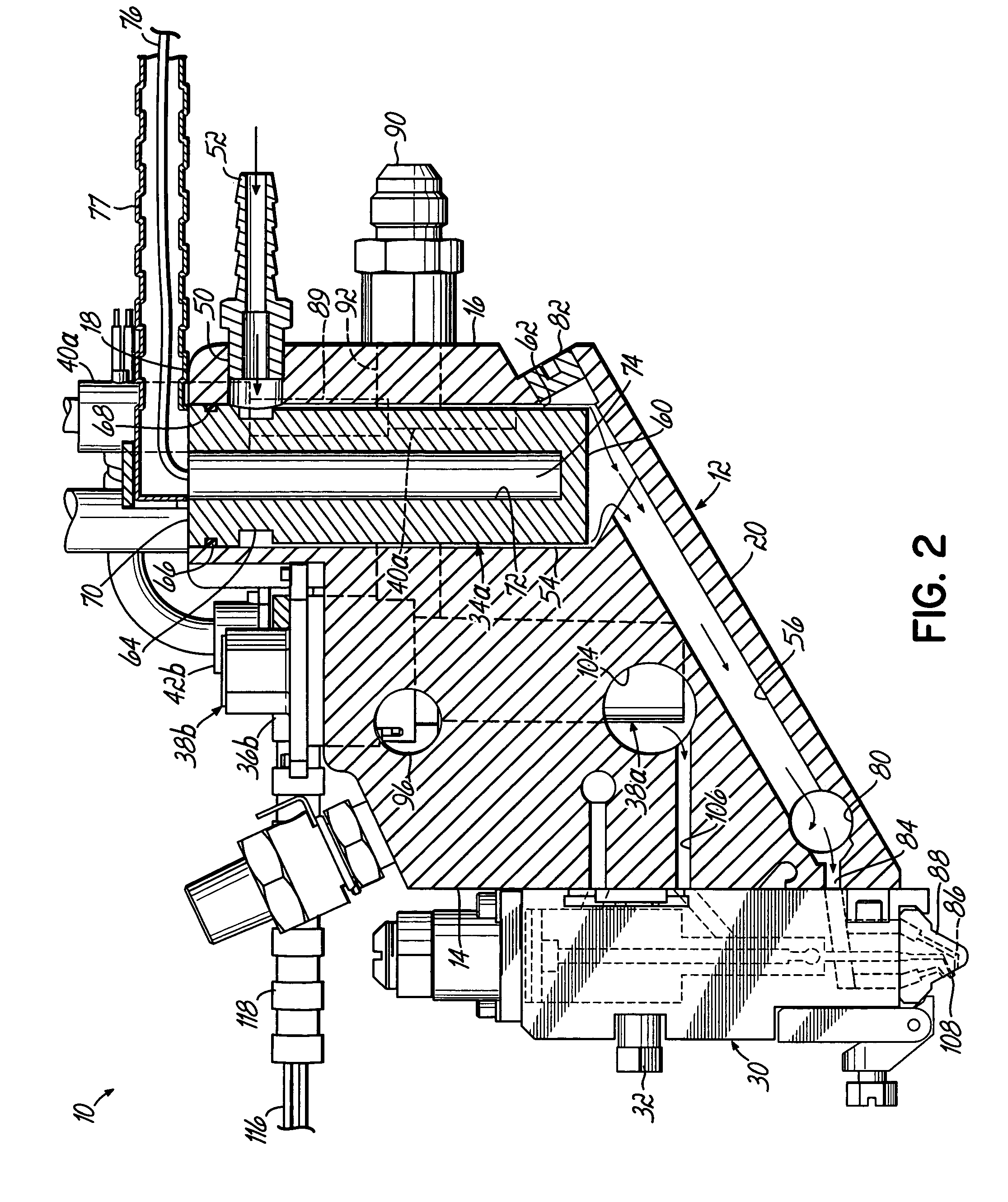
[0023]Referring to FIG. 1, there is shown an exemplary liquid material dispenser 10 according to the present invention. The liquid material dispenser 10 includes a unitary manifold body 12 which has been formed and machined to accommodate the various components of the liquid dispensing system, as will be described more fully below. The manifold body 12 has oppositely disposed front and rear surfaces 14, 16, oppositely disposed upper and lower surfaces 18, 20, and oppositely disposed longitudinal ends 22, 24. The manifold body 12 is supported by support members 25a, 25b attached to the upper surface 18 of the manifold body 12.

[0024]Several liquid dispensing modules 30 are secured to the front surface 14 of the manifold body 12 by fasteners 32. The dispensing modules 30 may be on / off-type modules with internal valve structure for selectively dispensing liquid material in the form of one or more filaments. An exemplary module of this type is disclosed in U.S. Pat. No. 6,089,413, common...


PUM


Abstract

A manifold for a liquid material dispenser has a unitary manifold body with process air and liquid material passages formed therethrough. Heaters for heating the process air and liquid material are both coupled directly to the manifold body and cooperate to simultaneously heat both the air and liquid material. The air and liquid material heaters may be arranged in either a generally vertical orientation, or a horizontal orientation with respect to the manifold body. In one embodiment, the process air heater includes a cylindrical member which is substantially exposed to the process air to optimize heat transfer from the cylindrical member to the process air.

Description

FIELD OF THE INVENTION[0001]The present invention relates generally to liquid material dispensing systems, and more particularly to applicators for dispensing controlled patterns of thermoplastic material to a substrate.BACKGROUND OF THE INVENTION[0002]Dispensing systems for supplying liquid material and filaments in other forms are conventionally used to apply thermoplastic materials, such as hot melt adhesives, to various substrates during the manufacture of diapers, sanitary napkins, surgical drapes, and other substrates. Typically, liquid material and pressurized air are supplied to the dispenser where they are heated and distributed to one or more dispensing modules for application to the substrate. The heated liquid material is discharged from the dispensing module while pressurized air is directed toward the dispensed liquid to attenuate or draw down the dispensed liquid material and to control the pattern of the liquid material as it is applied to the substrate.[0003]Convent...

Claims


Application Information

Patent Timeline
Patent Type & Authority Patents(United States)
IPC IPC(8): H05B3/68B05B7/00B05B7/08B05B7/16B05C5/00B05C5/02B05C9/14
CPCB05B7/0861B05B7/1646B05C5/0275B05C5/001B05C5/0279
Inventor CLARK, STEVENGOULD, MARK A.JONES, KENNETH
Owner NORDSON CORP
Why Eureka
Try Eureka