
Airbag for head protection

a head protection and airbag technology, applied in the direction of pedestrian/occupant safety arrangement, vehicle components, vehicular safety arrangments, etc., can solve the problems of inflow of inflation gas and subject objects to considerable downward pressur

Inactive Publication Date: 2006-08-01
TOYODA GOSEI CO LTD
View PDF3 Cites 43 Cited by
  • Summary
  • Abstract
  • Description
  • Claims
  • Application Information

AI Technical Summary

Benefits of technology

[0007]An object of the present invention is to provide a head-protecting airbag which, in the event that an object is located in the deployment area of vertical chambers, deploys while suppressing pressure put on the object.
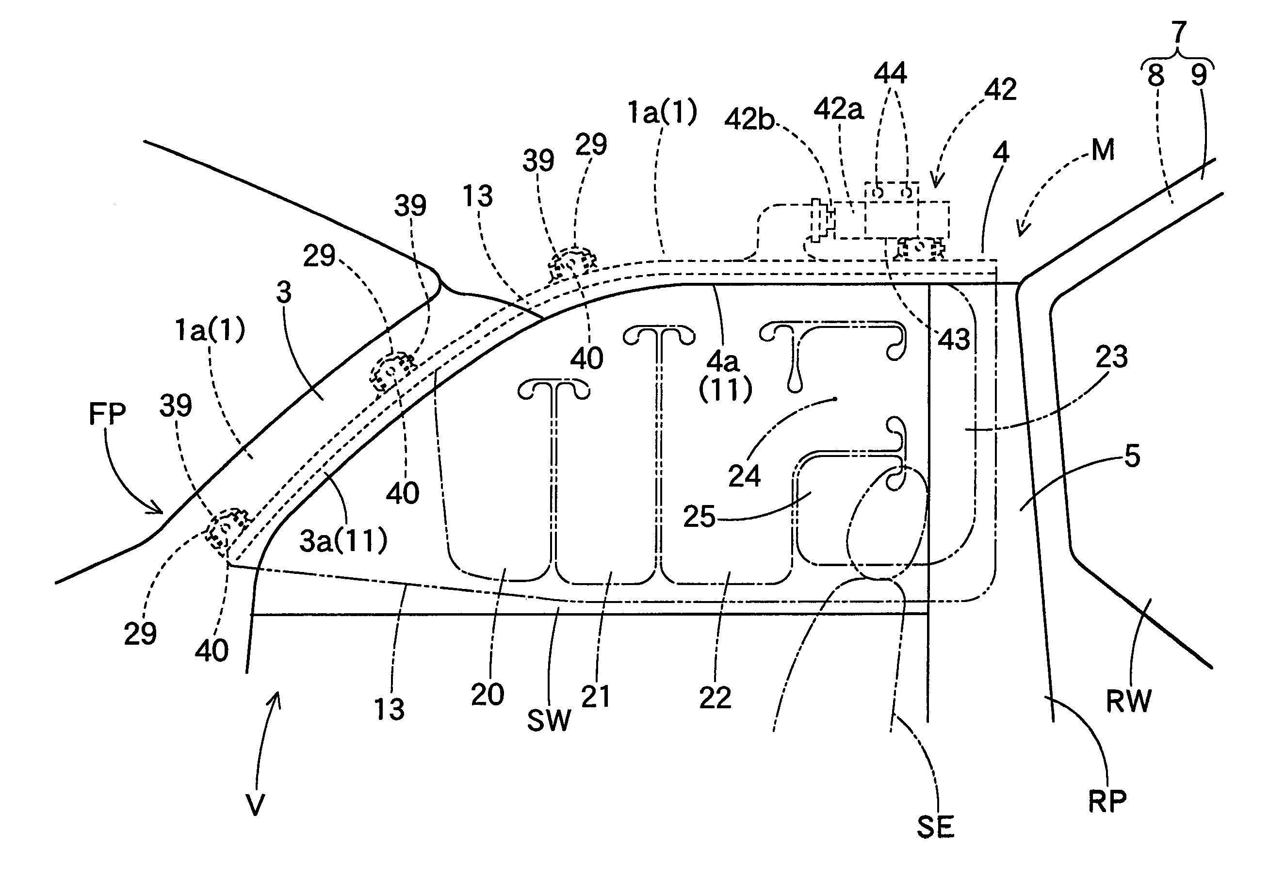
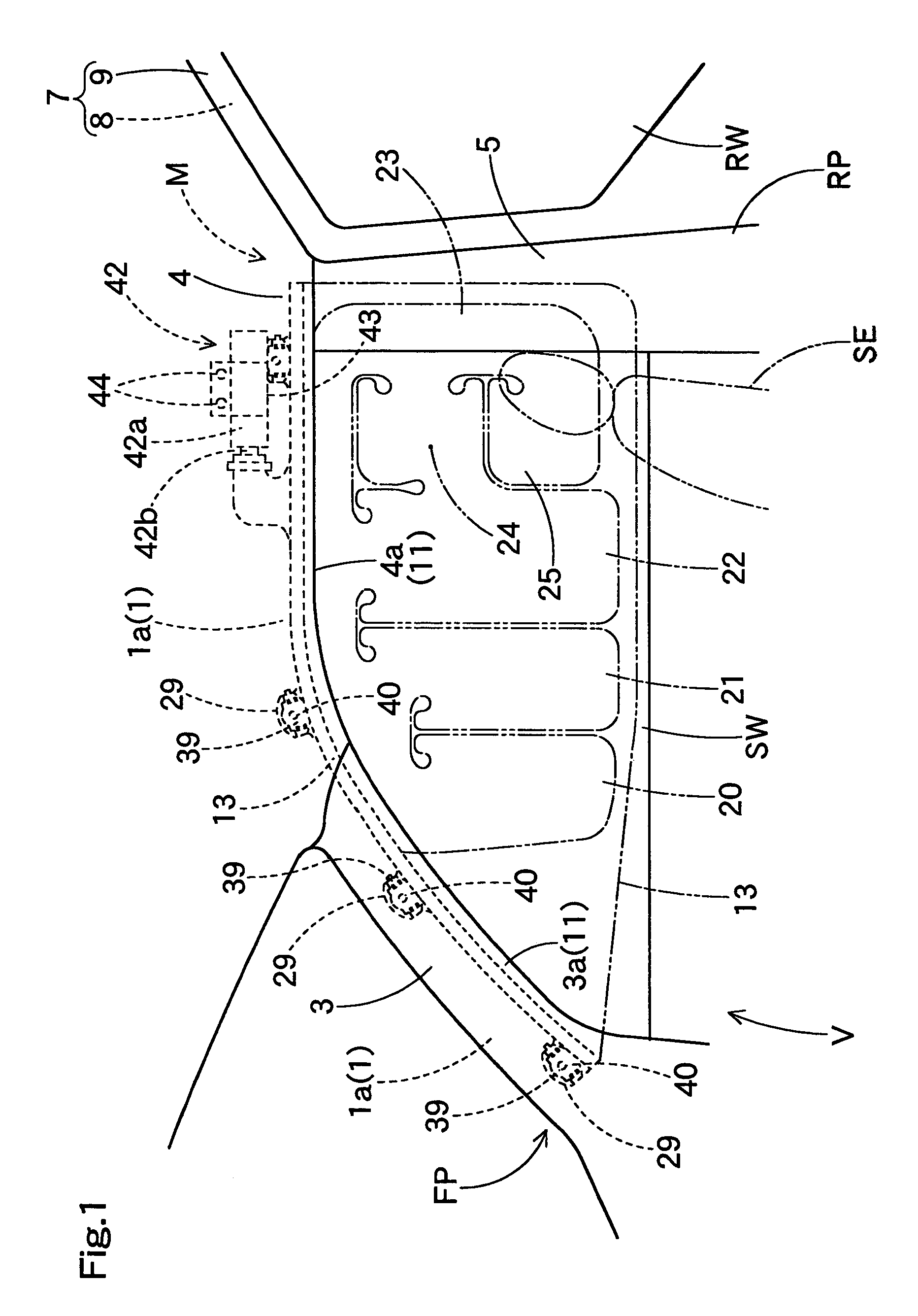
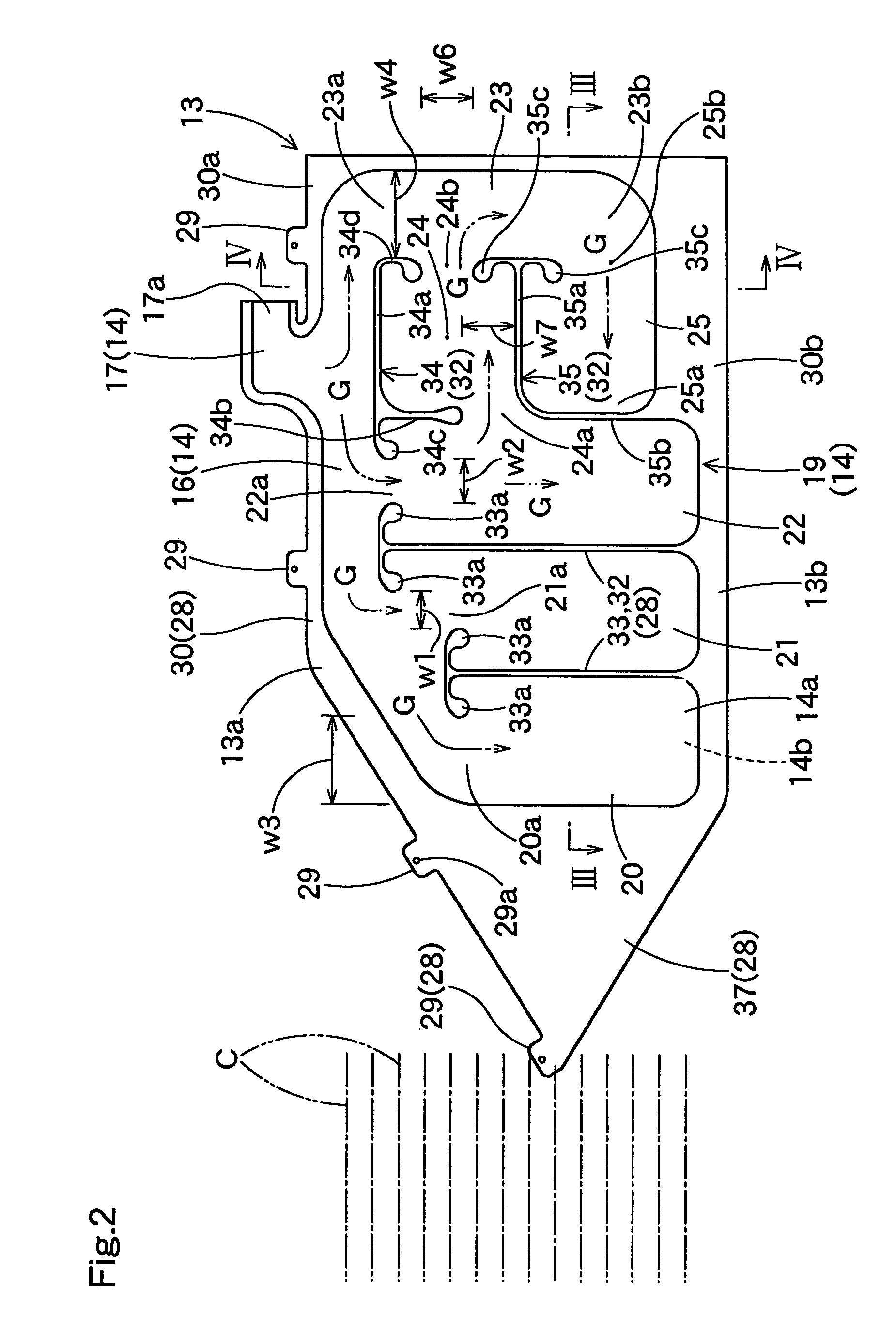
[0013]In the head-protecting airbag according to the present invention, a horizontal chamber inflatable along the longitudinal direction is located between the predetermined vertical inflatable chambers. Accordingly, in the course of airbag deployment, if an object interferes with one of the vertical chambers and blocks an entire area of the longitudinal width of the vertical chamber, inflation gas having flown into the vertical chamber is able to escape into the horizontal chamber. Consequently, even if an object like an occupant's head is positioned in the area of the vertical chamber in the course of airbag deployment, downward pressure put on the object is suppressed.
[0014]Therefore, even if an object is located in deployment area of the vertical chamber, the head-protecting airbag according to the present invention is able to deploy while suppressing pressure put on the object.
[0019]With this arrangement, the head-protecting airbag holds a wider protection area having cushioning property since the second horizontal chamber is located below the first horizontal chamber. The second horizontal chamber is closed at a side toward the vertical chamber that deploys in an area in which an object is located (as will be called the first vertical chamber), and admits inflation gas via the other vertical chamber (as will be called the second vertical chamber) upon deployment of the airbag. Accordingly, inflation gas having flown into the first vertical chamber runs through the first horizontal chamber and the second vertical chamber, and flows into the second horizontal chamber, namely, in a detouring manner. At this time, inflation gas also flows into the second vertical chamber vertically. However, since the second vertical chamber is communicated with the second horizontal chamber, and thus the second vertical chamber substantially comes to have a greater capacity, inflation gas having flown into the first horizontal chamber flows into the second vertical chamber smoothly, and then into the second horizontal chamber. In comparison with a case having no second horizontal chamber, therefore, the airbag is able to vent inflation gas to the first horizontal chamber smoothly when the object interferes with the first vertical chamber. Consequently, in the course of deployment, the airbag of the present invention is able to inflate while suppressing downward pressure on the object located in the first vertical chamber.

Problems solved by technology

With this arrangement, if an object like a vehicle occupant's head is positioned in a deployment area of one of the vertical chambers in the course of airbag deployment, especially if the object blocks an entire area of longitudinal width of the vertical chamber, the object may be subjected to considerable downward pressure along with inflow of inflation gas.

Method used


Image

  • Airbag for head protection
  • Airbag for head protection
  • Airbag for head protection

Examples


Embodiment Construction

[0027]A preferred embodiment of the present invention is described below with reference to the accompanying drawings. However, the invention is not limited to the embodiments disclosed herein. All modifications within the appended claims and equivalents relative thereto are intended to be encompassed in the scope of the claims.

[0028]Referring to FIG. 1, it is seen that a head-protecting airbag 13 is employed in a head-protecting airbag device M mountable on a single-cab vehicle V. The airbag 13 is normally folded and housed in lower edges of a front pillar FP and a roof side rail RR in the upper periphery of a door and a window SW inside the vehicle.

[0029]The airbag device M includes the airbag 13, an inflator 42, and an airbag cover 11.

[0030]The single-cab vehicle V includes a side window SW located at side of a seat in which a vehicle occupant is seated and located at side of the vehicle V, and a rear wall 7 located rearward of the window SW in a manner to intersect the window SW ...


PUM


Abstract

A head-protecting airbag according to the present invention is normally folded and housed in an upper edge of windows inside a vehicle, and includes a gas admissive portion inflatable with inflation gas from inflator and a non-admissive portion admitting no inflation gas. The gas admissive portion includes a shielding portion for covering the vehicle's interior side of the windows upon deployment of the airbag. The shielding portion includes a plurality of vertical chambers each of which is located vertically upon deployment of the airbag, and at least one horizontal chamber which is located along longitudinal direction of the vehicle upon deployment of the airbag. The horizontal chamber is located between at least one neighboring pair of the vertical chambers in the vicinity of vertically middle position of the pair of the vertical chambers, thereby communicating the pair of the vertical chambers.

Description

[0001]The present application claims priority from Japanese Patent Application No. 2003-035153 filed on Feb. 13, 2003, the entirety of which is hereby incorporated into the present application by this reference.BACKGROUND OF THE INVENTION[0002]1. Field of the Invention[0003]The present invention relates to a head-protecting airbag which is normally folded and housed in an upper edge of windows in the interior of vehicle, and is deployable to cover the interior side of the windows upon inflow of inflation gas.[0004]2. Description of Related Art[0005]In the prior art, Japanese Patent No. 3110709 is illustrative of a head-protecting airbag which includes a plurality of vertical chambers in an area of a shielding portion inflatable with inflation gas.[0006]In this conventional head-protecting airbag, each of the vertical chambers inflates by admitting inflation gas along the vertical direction upon deployment of the airbag. To paraphrase, each of the vertical chambers admits downward st...

Claims


Application Information

Patent Timeline
Patent Type & Authority Patents(United States)
IPC IPC(8): B60R21/16B60R21/20B60R21/00B60R21/232B60R21/233
CPCB60R21/232B60R2021/23316B60R2021/0048
Inventor OGATA, TETSUYA
Owner TOYODA GOSEI CO LTD
Learn More