Airbag module

a technology of airbags and modules, applied in the direction of vehicle components, pedestrian/occupant safety arrangements, vehicular safety arrangments, etc., can solve the problems of complex devices, high cost, and difficult to reduce manufacturing costs, and achieve the effect of reducing manufacturing costs

Inactive Publication Date: 2006-02-02
NIHON PLAST CO LTD
View PDF14 Cites 23 Cited by
  • Summary
  • Abstract
  • Description
  • Claims
  • Application Information

AI Technical Summary

Benefits of technology

[0005] This control device is complex and costly, thus making it difficult to reduce manufacturing costs.

Problems solved by technology

This control device is complex and costly, thus making it difficult to reduce manufacturing costs.

Method used


Image

  • Airbag module
  • Airbag module
  • Airbag module

Examples


Embodiment Construction

[0024] The airbag module according to an embodiment of the invention will be described with reference to the accompanying drawings.

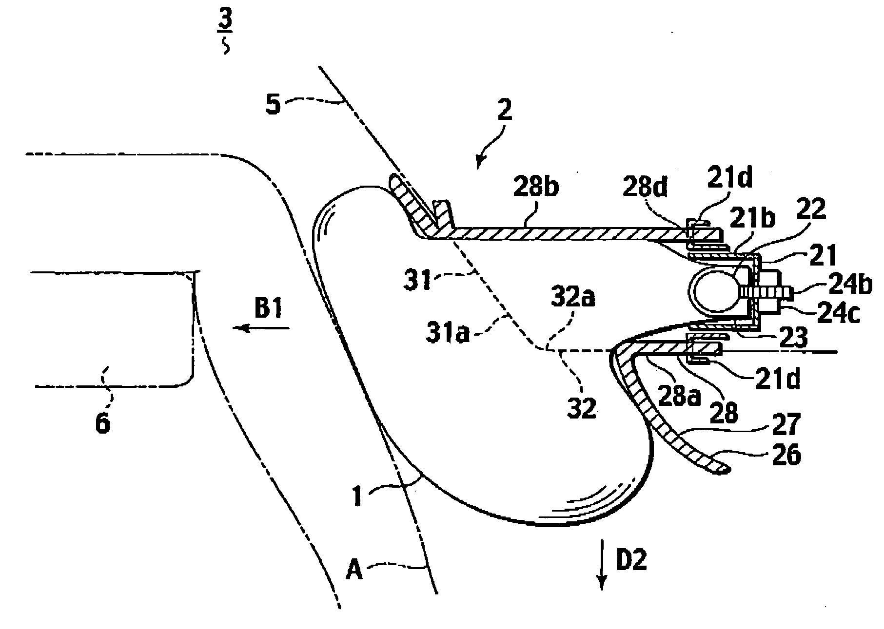
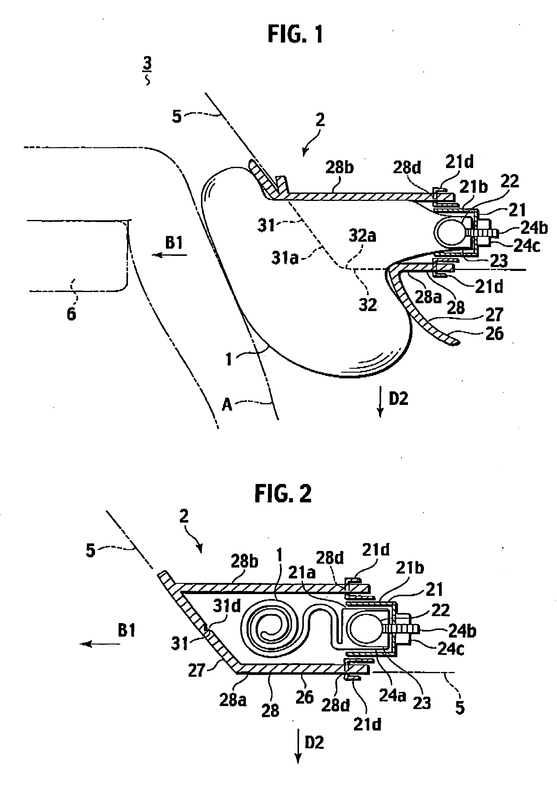
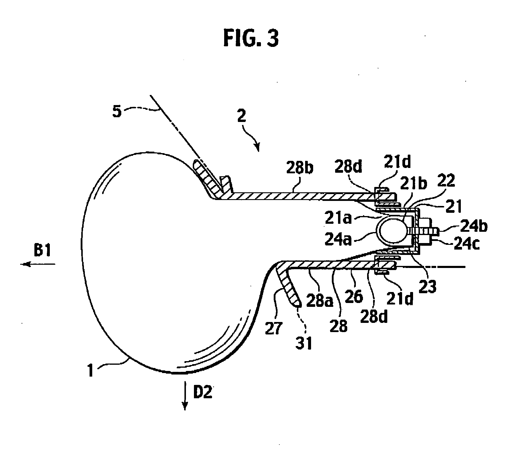
[0025] As illustrated in FIG. 1 to FIG. 3, an airbag module 2 with an airbag 1 is equipped to a panel 5 or a mounting face portion that faces the passenger compartment of the vehicle body of an automobile as a mounted member. This airbag module 2 faces the lower limbs of a passenger A including the knees as indicated with a chain double-dashed line in FIG. 1, and is referred to as a knee airbag module. The airbag module 2 develops to the underfoot of the passenger A to protect the legs of the passenger A when being subjected to an impact of a frontal collision.

[0026] In the following, directions such as a longitudinal direction will be based on the straightforward direction of a vehicle body 3. Specifically, the direction to the passenger A as a first direction will be defined as a backward direction B1. The opposite direction to this backward directio...


PUM


Abstract

An airbag module includes an airbag configured to receive a gas thereinto to develop toward lower limbs of a passenger seated. The airbag module includes a cover housing the airbag therein. The cover includes a first tear portion configured to tear by the airbag developing under pressures during development of the airbag for inflating the airbag in a first direction. The cover includes a second tear portion tearable by the airbag developing under pressures after tearing of the first tear portion for inflating the airbag in a second direction crossing the firs direction.

Description

CROSS-REFERENCE TO BELATED APPLICATIONS [0001] This application is based upon and claims the benefit of priority from Japanese Patent Application No. 2004-222499 filed on Jul. 29, 2004; the entire contents of which are incorporated herein by reference. BACKGROUND OF THE INVENTION [0002] This invention relates to an airbag module configured to develop, for example, toward the lower limbs of a passenger in a vehicle such as an automobile. [0003] The document of the related art discloses an airbag module configured to develop toward the lower limbs of a passenger seated in an automobile, which is referred to as a knee airbag module (e.g., see Japanese Patent Application Publication Laid-open No. 2002-337652, FIG. 1). This airbag module is disposed in an instrument panel below a steering wheel in front of a driver seat, or alternatively, below a glove box in front of a navigator seat, for example. When a control device detects a collision impact, gas is supplied from an inflator to deve...

Claims


Application Information

Patent Timeline
Patent Type & Authority Applications(United States)
IPC IPC(8): B60R21/20B60R21/16B60R21/205B60R21/215
CPCB60R21/206B60R21/2165B60R2021/23169B60R2021/161B60R21/231
Inventor UMEHARA, JUNICHI
Owner NIHON PLAST CO LTD
Why Eureka
Try Eureka