Wind turbine system

a wind turbine and system technology, applied in the direction of electric generator control, fluid couplings, couplings, etc., can solve the problems of poor wind turbine installation, poor wind turbine installation effect, and inability to meet the needs of wind turbines,

Inactive Publication Date: 2006-08-01
AEROVIRONMENT INC
View PDF27 Cites 80 Cited by
  • Summary
  • Abstract
  • Description
  • Claims
  • Application Information

AI Technical Summary

Benefits of technology

[0006]The invention is embodied in a wind turbine system that exploits an aerodynamically enhanced wind zone of a building by aligning a wind turbine generator, and preferably a plurality thereof, along the leading edge of its roofline. Each generator includes a structural support, a wind turbine rotor, and a generator set. The system includes a mounting assembly that attaches the generators to the upper edge of a wall of the building and that allows for easy retrofit attachment to existing structures. The system includes a busway extending along the mounting assembly and configured to provide electrical contact between the generator assembly and the electrical infrastructure of the building.

Problems solved by technology

However, such installations are very costly.
For example, proper location and mounting of wind generators can be an issue.
Thus, current approaches are typically limited to rural settings and are impractical in many other settings.

Method used


Image

  • Wind turbine system
  • Wind turbine system
  • Wind turbine system

Examples


Embodiment Construction

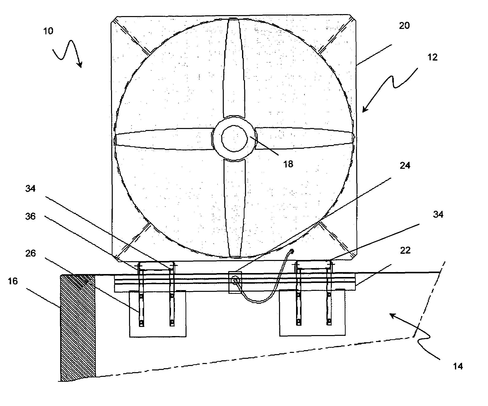
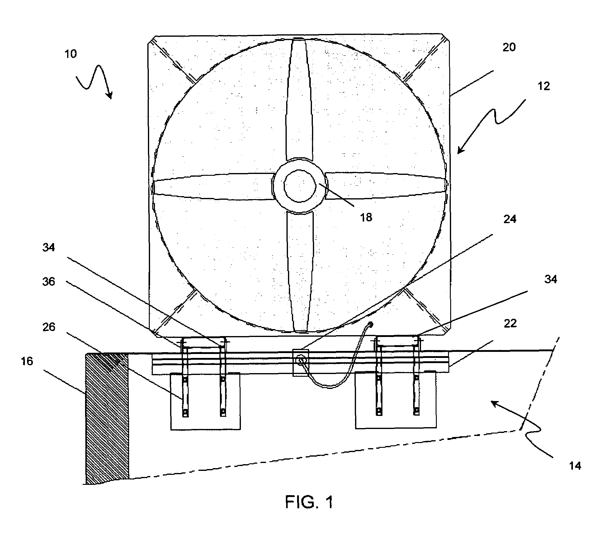
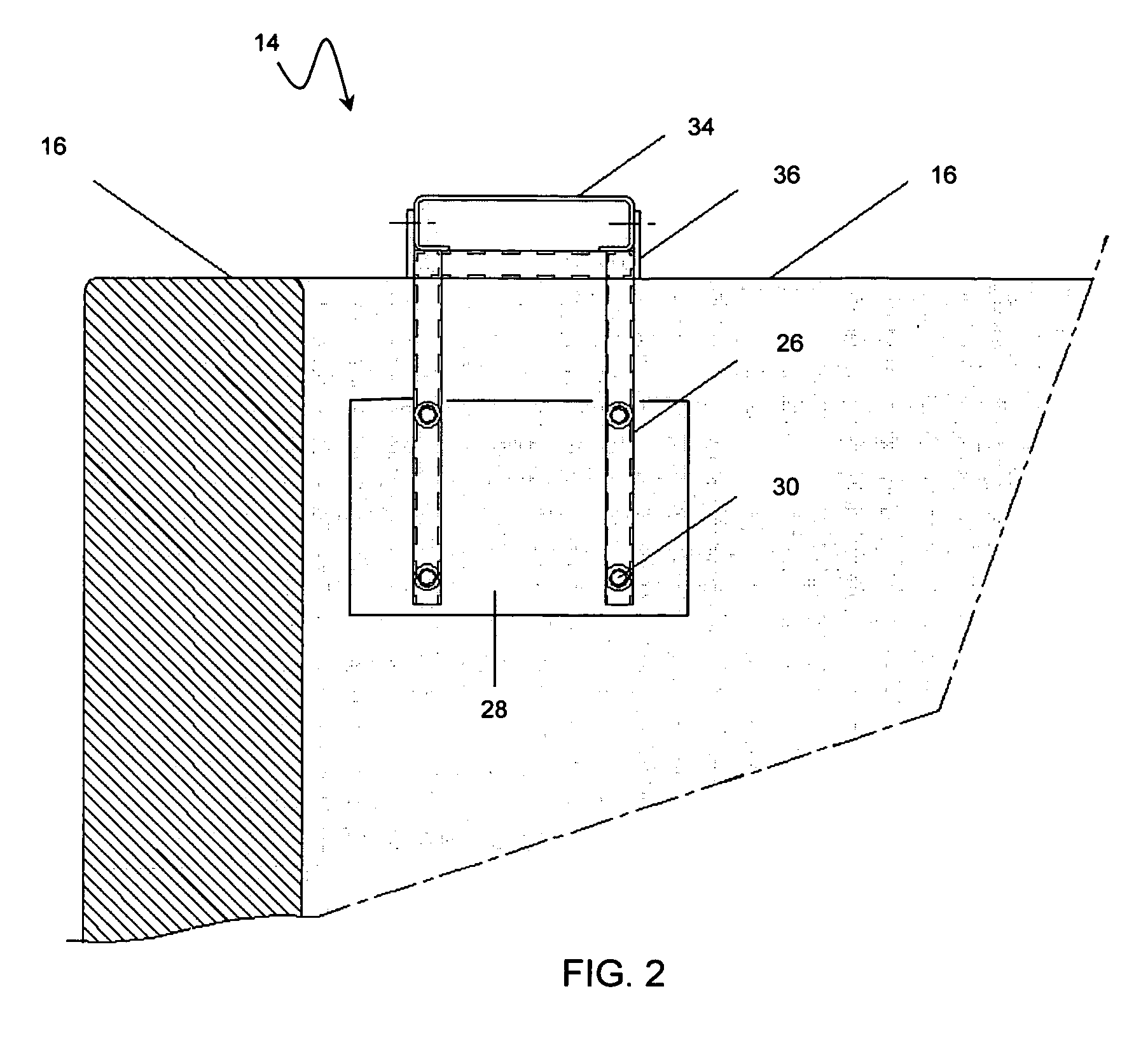
[0025]With reference to the illustrative drawings, and particularly to FIG. 1, there is shown a wind turbine system 10, including a generator 12 and a mounting assembly 14 for attaching the assembly to a wall 16. The wind turbine system preferably includes a plurality of wind turbine generators attached along a leading edge of a vertical wall, thereby exploiting an enhanced wind zone created as wind accelerates over the wall. Each generator includes a wind turbine rotor 18 and generator set (not shown) disposed in a structural support, e.g., box housing 20. The rotor drives the generator set, inducing the generation of electrical current. Each generator is configured to generate power in a range of about 50–100 watts and is in electrical contact with a DC busway 22 by an interconnect, e.g., plug 24. The DC busway feeds power to an inverter / controller (not shown) that interfaces with the building electricity infrastructure. Thus, the mounting assembly serves as both a structural and ...


PUM


Abstract

Wind turbine system, and related method, is provided that exploits an aerodynamically enhanced wind zone of a structure by aligning a wind turbine generator, and preferably a plurality thereof, along a wall thereof. Each generator includes a structural support, a wind turbine rotor and a generator set. The system includes a mounting assembly that attaches the generators to the upper edge of a wall of the building and that allows for easy retrofit attachment to existing structures. The system includes a busway extending along the mounting assembly and configured to provide electrical contact between the generator assembly and the electrical infrastructure of the building. Preferably, the generator assembly is mounted such that the rotor's axis of rotation is in a generally horizontal orientation. The system may further include a fairing attached to the mounting assembly and configured to extend outward from a front side of the wall. The fairing can be provided with a downwardly curved planar shape to facilitate airflow towards the rotors.

Description

BACKGROUND OF THE INVENTION[0001]The present invention relates generally to wind turbines and, more particularly, to wind turbines for use in small-scale applications. The present invention also relates to a method of using wind turbines in small-scale applications.[0002]Electrical generation from environmentally friendly sources, or “alternative energy sources,” has long been a goal of many, for both environmental and economic concerns. Wind-powered generators have been used for this purpose. Generally speaking, wind turbines transfer the wind's kinetic energy into electrical energy. This has been achieved by exposing a rotor to wind. The rotor turns a generator typically mounted aft of the rotor, driving the generator to create electricity. The rotor and generator combination (i.e., wind turbine generator) is mounted at the top of a tower high above the ground to expose it to high winds. The tower is attached to a foundation and is configured to endure significant structural loads...

Claims


Application Information

Patent Timeline
Patent Type & Authority Patents(United States)
IPC IPC(8): F03D9/00F03D11/04
CPCF03D11/04F05B2220/706F05B2240/13F05B2240/40F05B2240/911Y02B10/70Y02B10/30Y02E10/465Y02E10/725Y02E10/728F05B2260/30F03D9/25F03D13/20Y02E10/46Y02E10/72
Inventor ZAMBRANO, THOMASMACCREADY, TYLERWALKER, STEL N.
Owner AEROVIRONMENT INC
Why Eureka
Try Eureka