Speed sensorless control of an induction machine using a PWM inverter with output LC filter

a technology of inverter and sensor, which is applied in the direction of motor/generator/converter stopper, dynamo-electric gear control, dynamo-electric converter control, etc., can solve the problems of increased losses and acoustic noise, unwanted effects of motor, and increased motor control difficulty

Inactive Publication Date: 2006-08-01
ABB OY
View PDF17 Cites 25 Cited by
  • Summary
  • Abstract
  • Description
  • Claims
  • Application Information

AI Technical Summary

Problems solved by technology

The use of a PWM inverter, however, not only brings advantages but also causes unwanted effects in the motor.
The oscillation at the switching frequency causes additional losses and acoustic noise.
Adding an LC filter to a variable speed drive makes the motor control more difficult.
However, a speed sensorless control methods for induction motor supplied through an LC filter are not yet published.
A problem associated with the prior art control systems with an output filter is the need for either the measurements of current or voltage from the motor or the use of speed encoders.
Both of the above solutions can increase costs both for installation and maintenance on the system.

Method used


Image

  • Speed sensorless control of an induction machine using a PWM inverter with output LC filter
  • Speed sensorless control of an induction machine using a PWM inverter with output LC filter
  • Speed sensorless control of an induction machine using a PWM inverter with output LC filter

Examples


Embodiment Construction

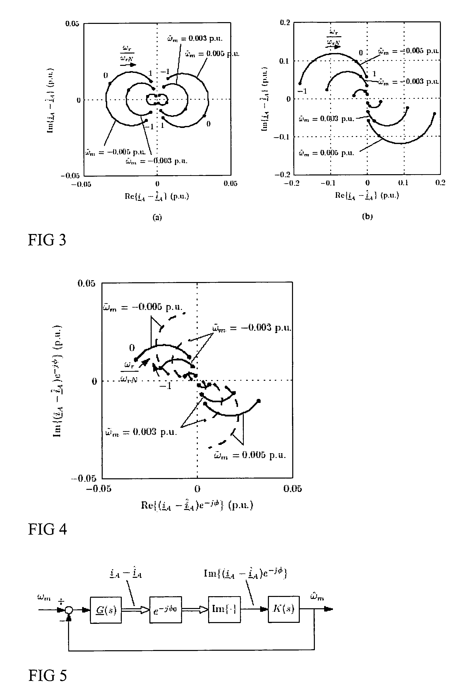
[0020]In the following first the system model and control are explained. Then attention is given to dynamic analysis of the system and simulation and experimental results are also described.

[0021]System Model and Control

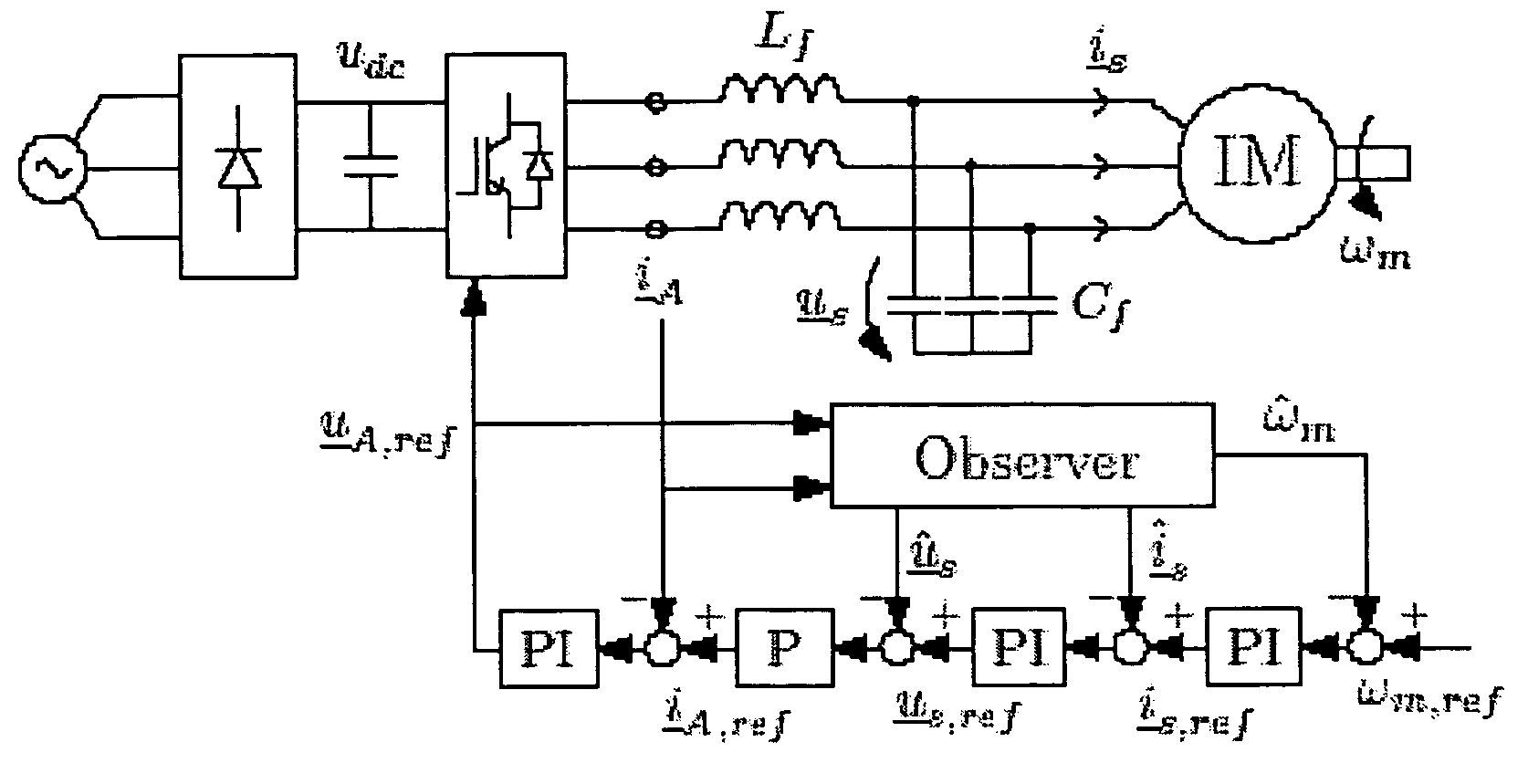
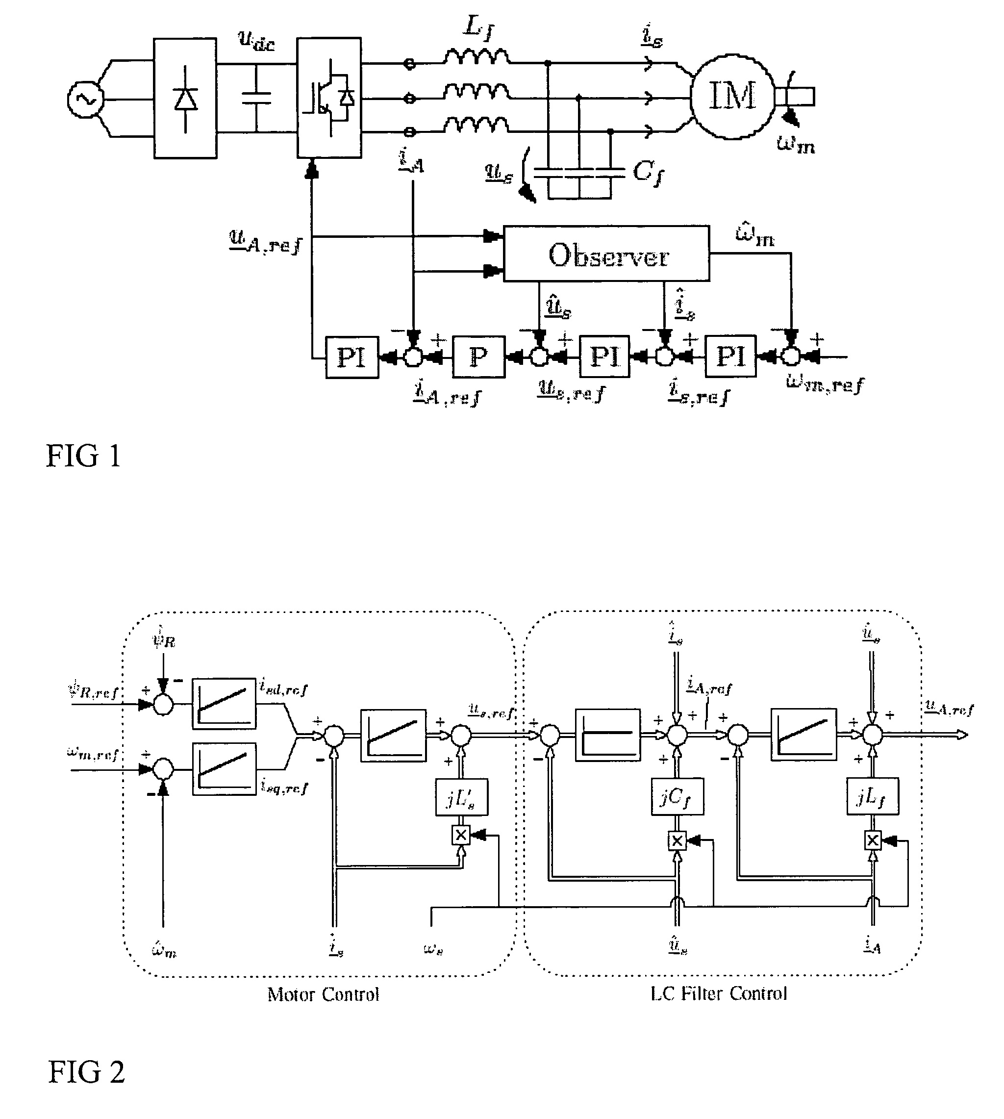
[0022]A principle of the control system is shown in FIG. 1. The inverter output voltage uA is filtered by an LC filter, and the induction motor (IM) is fed by the filtered voltage us. The inverter output current iA and the dc link voltage udc are the only measured quantities, whereas the stator voltage us, stator current is, and the electrical angular speed ωm of the rotor are estimated by an observer (the estimated quantities being marked by ‘^’). The system is controlled by nested control loops in estimated rotor flux reference frame. It should be noted that the control arrangement presented is only one example of suitable control.

[0023]A. Filter and Motor Models

[0024]In a reference frame rotating at angular frequency ωs, the equations for the LC filter are

[0025]ⅆi...


PUM


Abstract

A method of controlling of an induction machine using an inverter is disclosed with output LC filter. The method includes determining an inverter output current vector (iA), determining an inverter output voltage vector (uA), and forming a full-order observer having a system matrix (Â) and gain vector (K). The observer produces an estimated rotor flux linkage vector ({circumflex over (ψ)}R), an estimated stator current vector (îs), an estimated stator voltage vector (ûs) and an estimated inverter output current vector (îA). An estimation error (iA−îA) of the inverter output current vector is determined, and a speed adaptation law is formed based on the estimation error of the inverter output current vector for determining an estimate for electrical angular speed ({circumflex over (ω)}m) of the induction machine. The induction machine is controlled based on the produced estimates and a measured inverter output current.

Description

[0001]This application claims priority under 35 USC § 119 to EP Patent Application No. 04104340.7, the disclosure of which is hereby incorporated by reference in its entirety.FIELD OF THE INVENTION[0002]This invention relates to a speed sensorless control method for an induction motor that is supplied by a PWM inverter through an output LC filter.BACKGROUND OF THE INVENTION[0003]A voltage source PWM inverter enables stepless speed and torque control of AC motors, allowing reduced energy consumption and increased control performance. The use of a PWM inverter, however, not only brings advantages but also causes unwanted effects in the motor. The output voltage of the inverter consists of sharp-edged voltage pulses, producing bearing currents and high voltage stresses in motor insulations [1], [2]. The oscillation at the switching frequency causes additional losses and acoustic noise. These phenomena can be eliminated by adding an LC filter to the output of the PWM inverter. In additi...

Claims


Application Information

Patent Timeline
Patent Type & Authority Patents(United States)
IPC IPC(8): H02P23/12H02P21/13
CPCH02P21/13
Inventor SALOMAKI, JANNE
Owner ABB OY
Why Eureka
Try Eureka