Phase current detection method, inverter control method, motor control method, and apparatuses used in these methods

a technology of inverter control and phase current, which is applied in the direction of electric generator control, dynamo-electric converter control, dynamo-electric gear control, etc., can solve the problems of distorted current waveform, increased cost of motor driving apparatus, and increased measurement error in phase current, so as to eliminate the affection of noise, simplify the arrangement, and achieve the effect of noise measurement with eas

Inactive Publication Date: 2007-02-06
DAIKIN IND LTD
View PDF29 Cites 39 Cited by
  • Summary
  • Abstract
  • Description
  • Claims
  • Application Information

AI Technical Summary

Benefits of technology

[0136]When the phase current detection apparatus consistent with an embodiment of the invention is employed, the apparatus employs means for calculating the gate-pulse width so that the length of the command voltage vector and the vector output period are equal to one another, in response with the fact that the vector output period is longer than the minimum vector output period, as the minimum pulse width varying means. Therefore, the current detection can securely be realized with suppression of distortion in waveform, in addition to the operation and effect similar to those consistent with other embodiments of the invention.
[0137]When the phase current detection apparatus consistent with an embodiment of the invention is employed, the apparatus connects the converter for carrying out switching operation to the PWM inverter in series, and employs means for prohibiting switching of the converter and the PWM inverter at the current detection timing, as the converter inverter control means. Therefore, the current detection can be realized by removing the affection of noise.
[0138]When the phase current detection apparatus consistent with an embodiment of the invention is employed, the apparatus provides a current detection section which is in series with respect to the smoothing condenser on the DC link detects so that the converter current and the inverter current are detected. Therefore, the arrangement can be simplified and the measure for noise can be realized with ease, in addition to the operation and effect similar to those consistent with other embodiments of the invention.

Problems solved by technology

A disadvantage arises in that the motor driving apparatus is increased its cost in its entirety because the DC current transformer is expensive, when the method (1) is employed.
When the method (2) is employed, a pulse width becomes extremely thin depending upon the driving condition so that measurement error in phase current becomes greater.
When such measure is carried out, disadvantages arise in that a current waveform is distorted, and that a phase current is impossible to be detected at starting timing of a motor.
Specifically, when a phase current is detected based upon an inverter input, as is illustrated in “Method For Detecting Three Phase Output Current Of PWM Inverter At DC Side”, by Tanizawa et al., IEA-94-17 (hereinafter, referred to as cited document), a pulse width becomes thin at a portion in which phase voltage outputs are adjacent so that disadvantages arise in that great error is generated in phase current detection and that a phase current becomes impossible to be detected.
But, a disadvantage arises in that a current waveform becomes distorted due to the deformation of PWM.

Method used


Image

  • Phase current detection method, inverter control method, motor control method, and apparatuses used in these methods
  • Phase current detection method, inverter control method, motor control method, and apparatuses used in these methods
  • Phase current detection method, inverter control method, motor control method, and apparatuses used in these methods

Examples


Embodiment Construction

[0172]Hereinafter, referring to the attached drawings, we explain the embodiments of the phase current detection method, inverter controlling method and apparatus thereof according to the present invention.

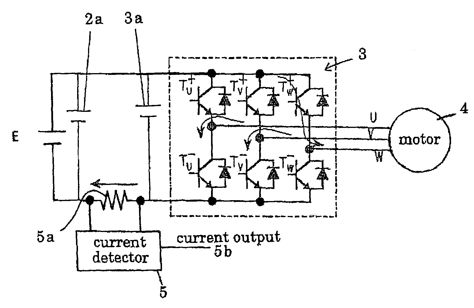
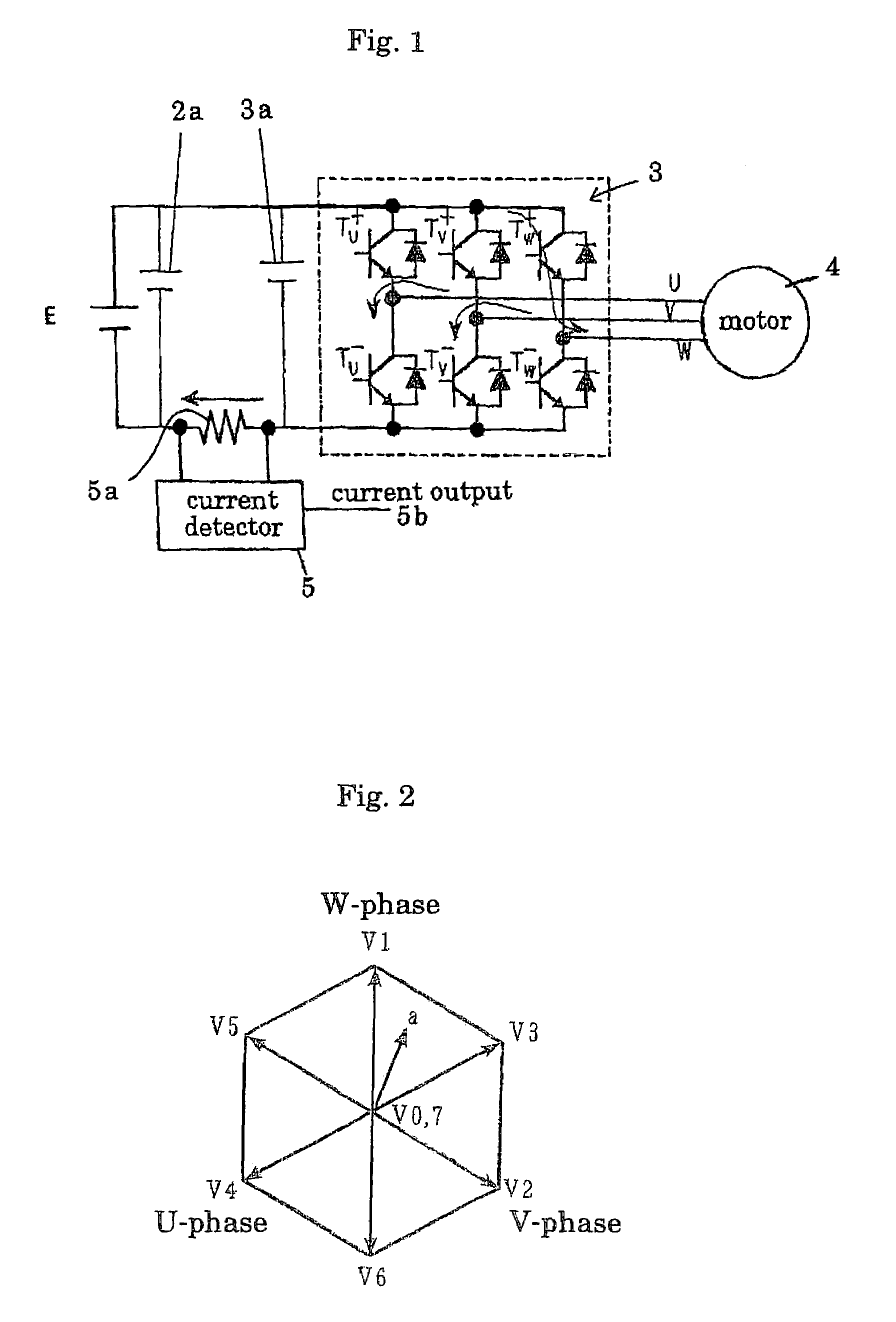
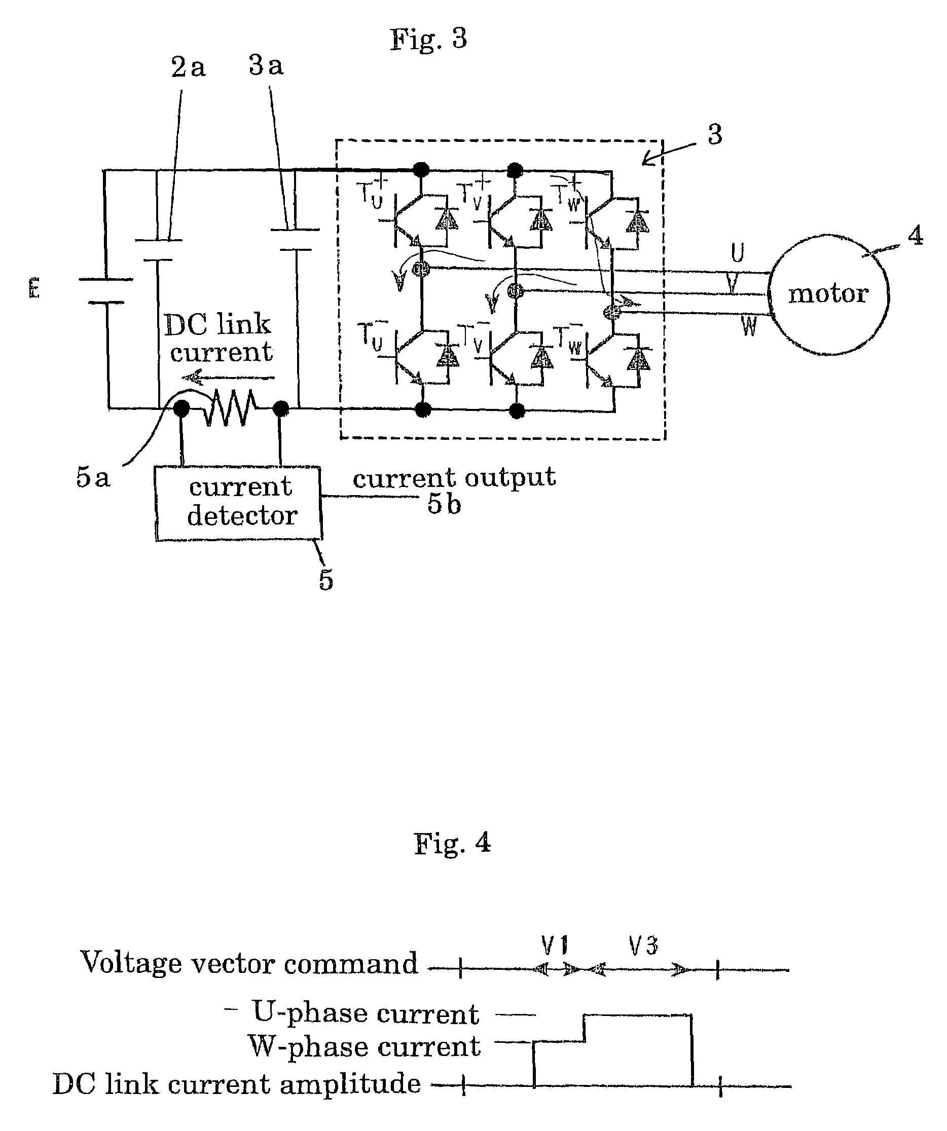
[0173]FIG. 1 is a diagram illustrating an arrangement of a motor driving apparatus using an inverter. Table 1 represents a relationship between an output voltage vector of an inverter (power devices) and a switching condition of a switching device.

[0174]

TABLE 1Tu+Tv+Tw+V0OFFOFFOFFV1OFFOFFONV2OFFONOFFV3OFFONONV4ONOFFOFFV5ONOFFONV6ONONOFFV7ONONON

Wherein, Tu+, Tv+ and Tw+represent switching devices of upper arm of u-phase, v-phase and w-phase, respectively. Ts+MAX(Toff)represent switching devices of lower arm of u-phase, v-phase and w-phase, respectively. In Table 1, ON represents a condition that the switching device of upper arm is ON and the switching device of lower arm is OFF, and OFF represents a condition that the switching device of upper arm is OFF and the switching device o...


PUM


Abstract

Apparatus and methods for phase current detection used for driving a motor by supplying outputs from a pulse width modulation (PWM) converter to the motor. One method presented provides detecting a DC link current and a vector pattern, determining whether a voltage vector lengths exceeds a predetermined value, and adjusting the voltage vector by adding a positive or reversed voltage based upon the above determination and an integrated error value.

Description

[0001]This application is the national phase under 35 U.S.C. § 371 of PCT International Application No. PCT / JP02 / 10132 which has an International filing date of Sep. 27, 2002, which designated the United States of America.TECHNICAL FIELD [0002]The present invention relates to a phase current detection method, Inverter control method, motor control method and apparatus for carrying out these methods. More particularly, the present relates to a phase current detection method, inverter control method, motor control method and apparatus for carrying out these methods which are included in a motor driving apparatus for driving a motor by supplying output from a PWM inverter to the motor, and which are suitable for detecting phase current of the motor based upon a DC link current and a vector pattern to be applied and for carrying out current controlling or position-sensor-less controlling.RELATED ART [0003]From the past, it is generally carried out that motor phase currents are detected ...

Claims


Application Information

Patent Timeline
Patent Type & Authority Patents(United States)
IPC IPC(8): H02P27/04H02P21/00H02P21/18H02P21/24H02P23/14H02P27/06
CPCH02M7/53873H02M7/53875H02P6/002H02P27/06H02M2001/0009H02M7/5395H02M2007/53876H02P6/28H02M1/0009H02M7/53876
Inventor MAEDA, TOSHIYUKITANIGUCHI, TOMOISA
Owner DAIKIN IND LTD
Why Eureka
Try Eureka